


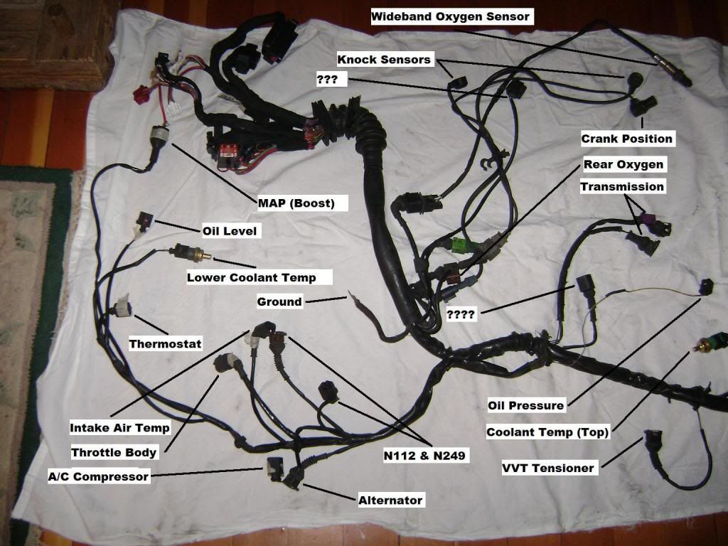
MAP Sensor
Connector: Black (4 pin)
1: Black
2: Empty
3: White with black stripe
4: Grey with blue stripe
Oil Level
Connector: Black (3 pin)
1: Black with red stripe
2: Brown
3: Red with green stripe
Thermostat (possibly wrong)
Connector: Black (2 pin)
1: Brown
2: Blue with brown stripe
Lower Coolant Temp Sensor
Connector: Black (2 pin)
1: Yellow with black stripe
2: Blue with black stripe
Throttle Body
Connector: Black (6 pin)
1: Purple with red stripe
2: Green with purple stripe
3: Red with purple stripe
4: Purple with red stripe
5: Brown with purple stripe
6: Grey with brown stripe
A/C Compressor (possibly wrong)
Connector: Black (2 pin)
1: Blue
2: Blue
IAT
Connector: Black (2 pin)
1: Black with red stripe
2: Black
Alternator (possibly wrong)
Connector: Black (2 pin)
1: Green with blue stripe
2: White with green stripe
N112
Connector: Brown (2 pin)
1: Green with yellow stripe
2: Brown with black stripe
N249
Connector: Black (2 pin)
1: Green with yellow stripe
2: Yellow with green stripe
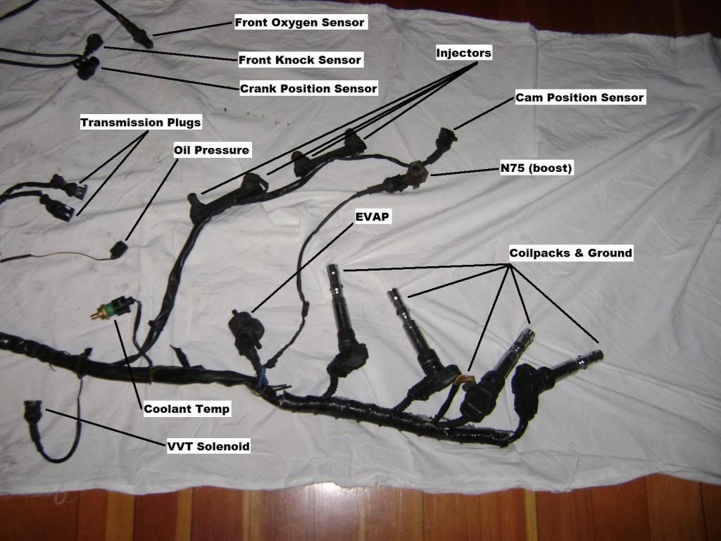
Wideband 02
Connector: Black (6 pin)
1: White
2: Black with white stripe
3: Green with yellow stripe
4: Red with white stripe
5: Brown
6: Grey with green stripe
Rear 02 Sensor
Connector: Brown (4 pin)
1: Green with yellow stripe
2: White with grey stripe
3: Purple
4: Red
Crank Position
Connector: Grey (3 pin)
1: Black
2: Blue
3: Grey
Knock Sensor (Rear)
Connector: Blue (3 pin)
1: Yellow
2: Green
3: Black
Knock Sensor (Front)
Connector: Green (3 pin)
1: White
2: Brown
3: Black
???
Connector: Black (3 pin)
1: Blue with yellow stripe
2: Empty
3: Brown with yellow stripe
Oil Pressure
Connector: Black (1 pin)
1: Yellow
Speed Sensor (Trans)
Connector: Black (3 pin)
1: Empty
2: Brown
3: Brown with red stripe
Other Trans Sensor (??)
Connector: Black (5 pin)
1: Empty
2: Blue with red stripe
3: Black with blue stripe
4: Empty
5: Empty
????
Connector: Black (1 pin)
1: Red with black stripe
VVT Tensioner
Connector: Black (2 pin)
1: Green with blue stripe
2: Yellow with grey stripe
Coolant Temp (Top)
Connector: Black (4 pin)
1: Blue with brown stripe
2: Brown with yellow stripe
3: Black
4: Brown with grey stripe
Cam Position Sensor
Connector: Black (3 pin)
1: White with black stripe
2: Green with grey stripe
3: Black
Injector 1 (Front)
Connector: Black (2 pin)
1: Red with blue stripe
2: Black with green stripe
Injector 2
Connector: Black (2 pin)
1: Red with blue stripe
2: Brown with blue stripe
Injector 3
Connector: Black (2 pin)
1: Red with blue stripe
2: Grey with green stripe
Injector 4
Connector: Black (2 pin)
1: Red with blue stripe
2: Grey with purple stripe
N75
Connector: Black (2 pin)
1: Black with purple stripe
2: Yellow with white stripe
EVAP
Connector: Black (2 pin)
1: Green with yellow stripe
2: Purple
Coilpack 4 (Rear)
Connector: Black (4 pin)
1: Red with green stripe
2: Brown
3: Brown with black stripe
4: Brown with yellow stripe
Coilpack 3
Connector: Black (4 pin)
1: Red with green stripe
2: Brown
3: Grey with black stripe
4: Brown with yellow stripe
Coilpack 2
Connector: Black (4 pin)
1: Red with green stripe
2: Brown
3: Grey with brown
4: Brown with yellow stripe
Coilpack 1 (Front)
Connector: Black (4 pin)
1: Red with green stripe
2: Brown
3: Grey
4: Brown with yellow stripe
Coilpack Grounds: Brown with yellow stripe
************************************************** **************************************
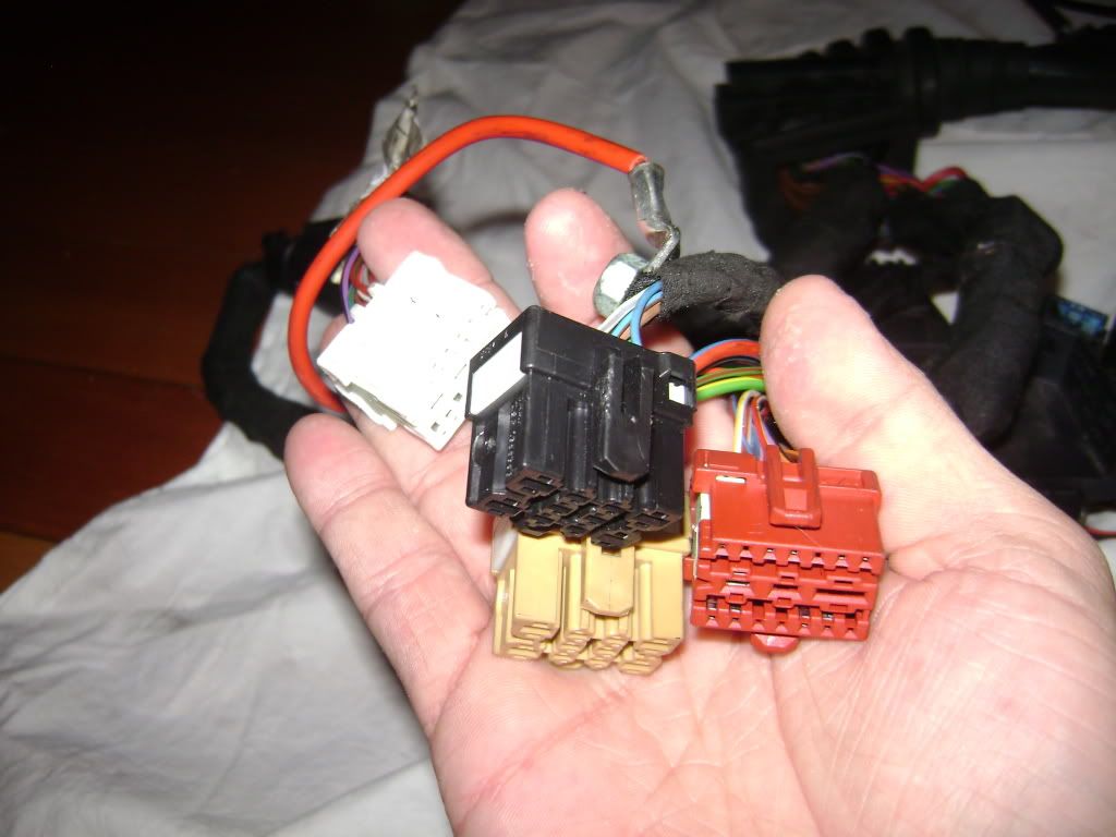
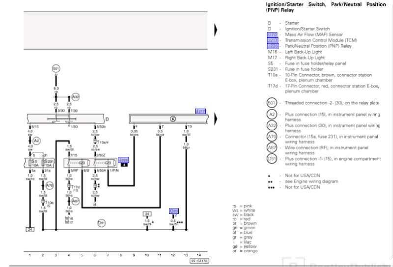
2000 Audi S4 Body Harness Plugs:
- T10, Brown, 10 pin
1. green/red - K-line diag wire into ECU pin 43
2. green/brown - to pin 47 on ECU from ?
3. white/blue - vehicle speed signal to pin 54 on ECU
4. red/black - from park/neutral position relay to ignition/starter switch
5. black/blue - to pin 3 on back-up light switch
6. unused
7. unused
8. black/red - to pin 1 on oil level thermal sensor
9. red/grey - to pin 3 on oil level thermal sensor
10. yellow - to pin 81 on ECU from ?
- T10m, Black, 10 pin
1. blue - goes to the voltage regulator (D+/61)/generator
2. green/blue - rpm signal to pin 37 on ECU
3. white/grey - from cluster to oil pressure switch
4. red - from positive wire 30 to ECU pin 62
5. brown/yellow, pin 3 on engine coolant temp sensor
6. unused
7. blue/green - from cluster to pin 1 on Engine Coolant Level Warning Switch
8. red/blue - power pin 15 to fuel pump relay and then ECU
9. blue/brown - from cluster to ground connection 2?
10. brown/red - from cluster to to pin 2 on speedometer vehicle speed sensor (VSS)
- T10ar, Orange, 10 pin
1. red/green - from 20A fuse in fuse holder to power output stage pin 1 connector T5d
2. red/brown - to pin 48 on ECU from ?
3.
4. unused
5. black/blue - pin 1 on injector 1 to 20amp fuse in fuse holder
6. white/yellow - to pin 1 on leak detection pump
7. yellow/red - to pin 2 on leak detection pump
8. green/yellow - to 15A fuse in fuse holder
9.
10. blue/lilac - engine overhead warning light
- T15m, Red, 15 pin
1. green/brown - From ABS control module to ECU pin 74
2. unused (only for FWD)
3. black/green - A/C control head to ECU pin 41
4.
5. black/lilac - to pin 30 on ECU from ?
6.
7.
8.
9.
10.
11.
12.
13.
14. orange/brown - connection (low-bus)
15. orange/black - connection (high-bus)
- T15, White, 15 pin
1. yellow/blue - to pin 1 (4 on 2001) on throttle body
2. yellow/lilac - to pin 2 on throttle body
3. brown/red - to pin 3 on throttle body
4. green/yellow - to pin 4 (5 on 2001) on throttle body
5. green - to pin 5 (1 on 2001) on throttle body
6. brown/green - to pin 6 on throttle body
7. red/grey - to pin 1 on connector T6y
8. blue - to pin 2 on connector T6y
9. red/yellow - to pin 3 on connector T6y
10. black/white - to pin 6 on connector T6y
11. red/black - to pin 2 on brake light switch
12. white/red - to pin 4 on brake light switch
13. red/green - to pin 1 on clutch vacuum vent valve switch
14.
15.
************************************************** ********************************
2003 B6 A4 1.8T harness
T10, Black, 10 pin
1. blue - generator
2. unused
3. white/grey - Oil pressure switch
4. unused
5. red/green - from pin 121 on ECU to ?
6. brown/yellow - pin 3 from engine coolant level warning light
7. blue/yellow - Engine coolant level warning switch
8. unused
9. blue/brown - Engine coolant temp sensor
10. brown/red - Speedometer vehicle speed sensor pin 2 (unused in 03)
T10a, Brown, 10 pin
1. red/blue - from injector harness to... ?
2. black/red - Oil level thermal sensor pin 1
3. unused
4. red/black - Ignition/starter switch to ground
5. black/blue - Back up light switch pin 3
6. green/red - control module with indicator unit in instrument panel insert
7. unused
8. green/yellow - connector for fuse 234, connects MAF, N112, N80, N249
9. red/grey - Oil level thermal sensor pin 3 (red/green for 03)
10. unused
T17e, White, 17 pin
1. brown/green - to pin 1 on throttle body
2. yellow/lilac - to pin 2 on throttle body
3. brown/red - to pin 3 on throttle body
4. yellow/blue - to pin 4 on throttle body
5. grey/yellow - to pin 5 on Throttle Body
6. brown - to pin 6 on throttle body
7. unused
8. unused
9. unused
10. blue/green - from pin 38 ECU to steering column electronics module
11. red/black - to pin 4 on brake light switch from ECU
12. white/red - to pin 2 on brake light switch from ECU
13. red/green - to pin 2 clutch vacuum vent valve switch
14. grey/white - from pin 1 on locking relay for starter (clutch pedal switch) to pin 2 on clutch vent vacuum valve switch
15. black/lilac - from ? to ECU
16. red/grey - from power supply relay to fuse S229 (20A)
17. unused
T17d, Red, 17 pin
1. white/yellow - pin 1 leak detection pump to ECU
2. grey/red - pin 2 leak detection pump to ECU
3. unused
4. unused
5. blue/brown - ? (03)
6. lilac/blue - to airbag control module from pin 67 ECU
7. unused
8. unused
9. unused
10. red/blue - to pin 5 on fuel pump relay
11. red/white - to ECU pin 24 to coolant fan control module
12. unused
13. orange/brown - Wire connection (low-bus)
14. orange/black - Wire connection (high-bus)
15. blue/red - reverse lamp connector
16. unused
17. unused
************************************************** ************************************************
2004 B6 S4 4.2 harness
T10, Black, 10 pin
1. blue – generator ???
2.
3. white/green – from instrument panel to F1 (oil pressure switch)
4.
5.
6. brown/yellow – from pin 3 on F66 (Engine Coolant Level Warning Switch) to ground 269
7. blue/yellow – from J285 (dash) to pin 1 on F66 (Engine Coolant Level Warning Switch)
8.
9. blue/brown – from J285 (dash) to pin 1 on G2 (Engine Coolant Temperature Sensor)
10.
T10a, Brown, 10 pin
1. red/blue – from 25 to D95 ground for injector 1-6 ???
2. black/red – from 21 to pin 1 on G266 (Oil Level Thermal Sensor) ???
3.
4. red/black - to the 50 pin on the starter
5. black/blue – from connector A70 to F4 (Back-up light switch)
6. for auto cars
7.
8. green/yellow – from 26 to D22 ground
9. red/green – from instrument panel to pin 3 on G266 (Oil Level Thermal Sensor)
10.
T17e, White, 17 pin
1. brown/green – from throttle body pin 1 to ECU pin 72
2. yellow/lilac - from throttle body pin 2 to ECU pin 73
3. brown/red - from throttle body pin 3 to ECU pin 36
4. yellow/blue - from throttle body pin 4 to ECU pin 35
5. green/yellow - from throttle body pin 5 to ECU pin 33
6. brown - from throttle body pin 6 to ECU pin 34
7.
8.
9.
10. blue/green – from dash to ECU
11. red/black – pin 4 on brake light switch to ECU pin 56
12. white/red – pin 2 on brake light switch to ECU pin 55
13. green/grey – pin 2 on clutch vacuum vent valve switch to ECU pin 39
14.
15. black/lilac – from 20 to pin 21 on ECU
16. red/grey – from ECM power supply relay to fuse 229 (20A) to 229???
17.
T17d, Red, 17 pin
1. yellow - from pin 1 on leak detection pump to ECU pin 80
2. green/red – from pin 2 on leak detection pump to ECU pin 25
3. red/yellow – from coolant fan control module 2 to ECU pin 104
4.
5.
6. lilac/blue (possibly not there) – from fuse 234 to ECU pin 61???
7. green/black – from pin 1 on N220 valve for exhaust flap to ECU pin 22
8.
9.
10. red/blue – pin 4 on fuel pump relay to pin 65 on ECU
11. red/white – from coolant fan control module 1 to ECU pin 66
12.
13. orange/brown – CanBus (low) from instrument panel to pin 58 on ECU
14. orange/black – CanBus (high) from instrument panel to pin 60 on ECU
15. blue/red – from J393 (Central Control Module for Comfort System) to 220???
16.
17.

 Reply With Quote


Bookmarks