For those of you who like these kind of DIY write up threads here you go.
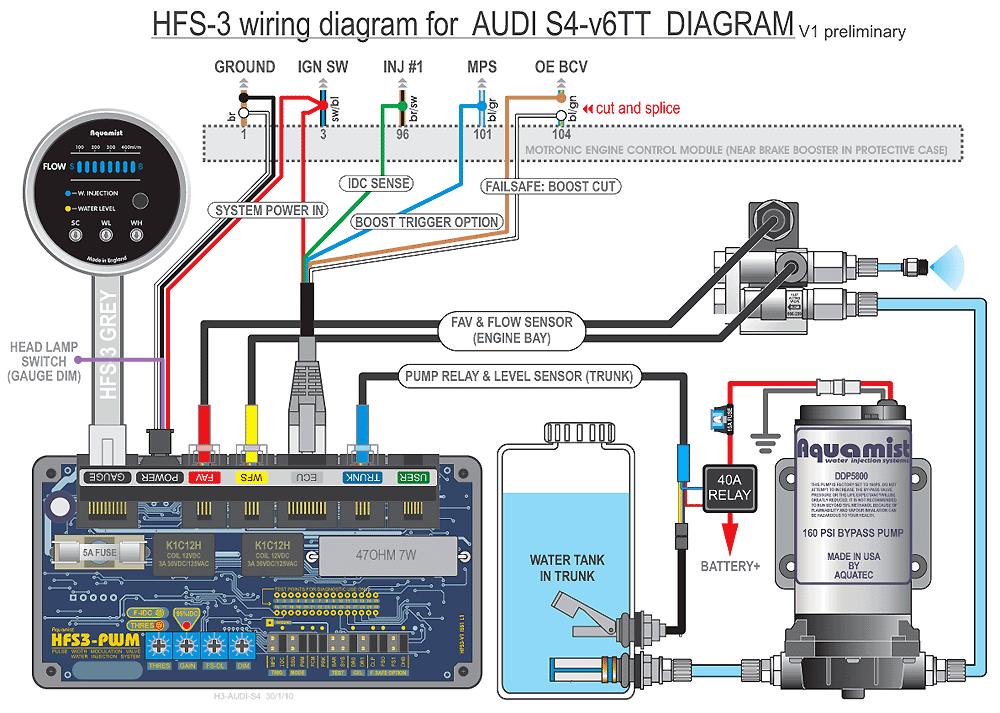
Using this wiring diagram as a guide, I started splicing away!
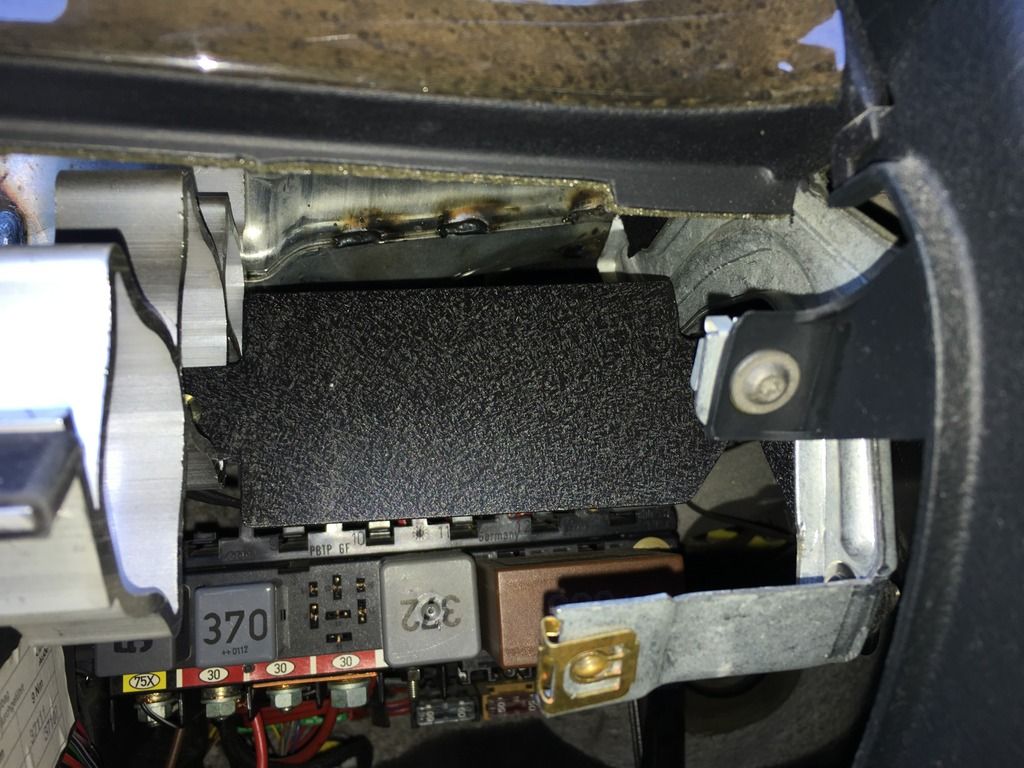
First made a little bracket to mount the controller and have a reference of the connector lengths. I didn't take any pics of the routing under the dash but went through an unused relay spot then up through the hole in the ECU box.
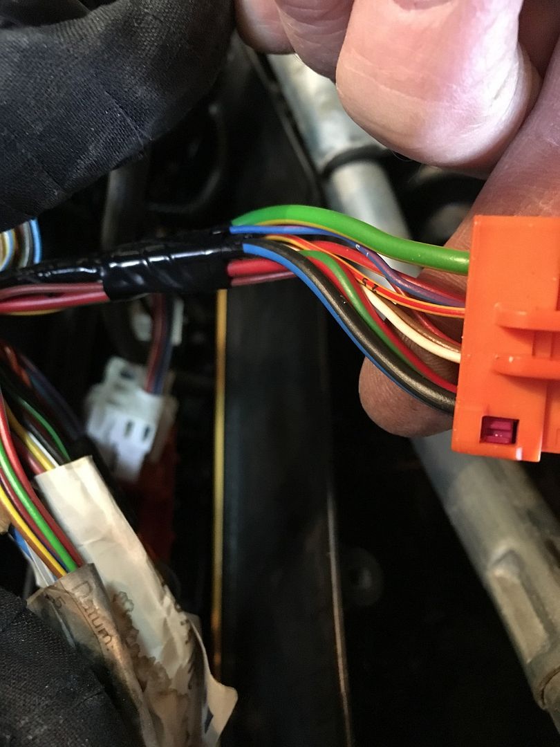
RED on the power plug and Red on the ECU plug jointed together and connected to the switched ignition power for the ECU (pin 3) at the Black with Blue stripe wire in Orange plug at the back of the ECU box. Note.... (Looking at the ignition switch wiring diagram this wire should have power while cranking and did when checking with a meter but the gauge still looks to turn off during cranking.) I still may try and find a connection at the elusive 15!!
White and Black ground wires joined together and ran down through existing wire harness to chassis grounding point in drivers foot well under fuse box.
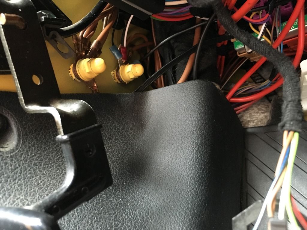
Purple gauge dim Wire routed in the the rear of fuse box and spliced into the switched side of fuse 23 Grey with black stripe(Tail and side marker Left)
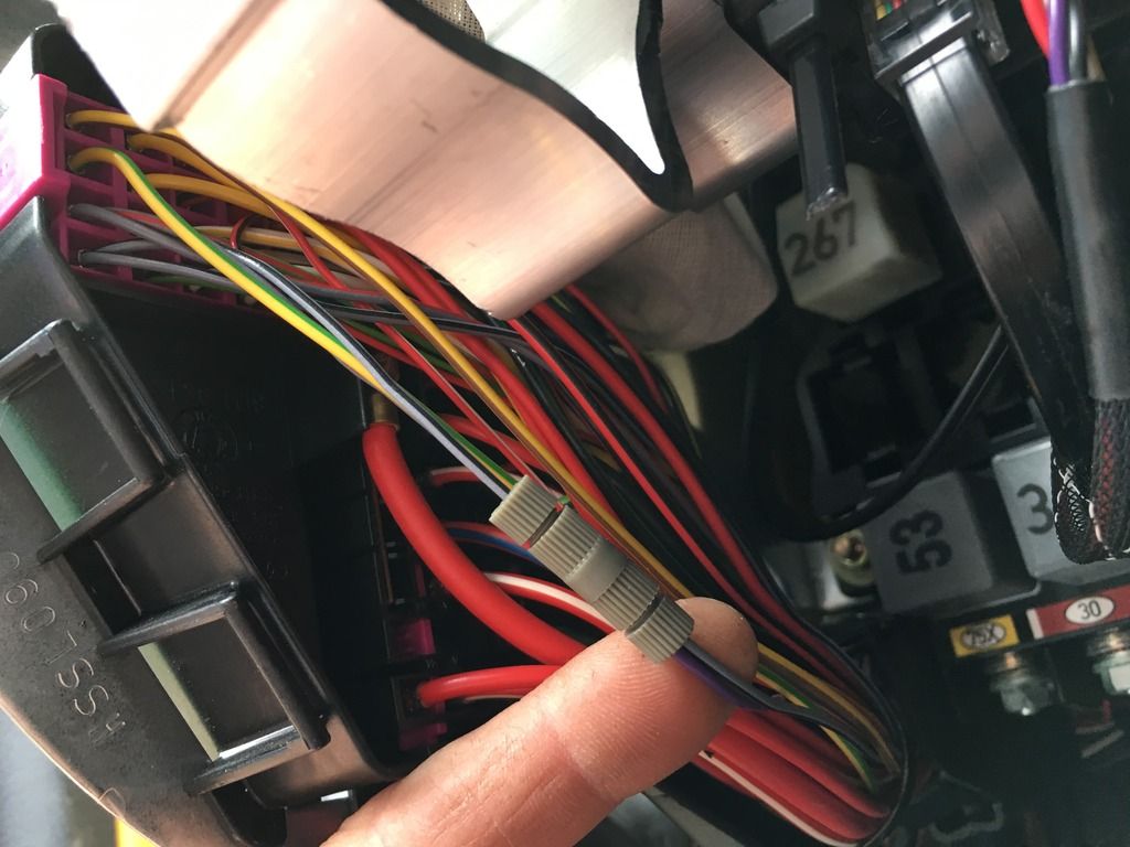
Green IDC sense spliced into the Brown with black stripe wire (ECU pin 9) found in the main ECU loom, small wire buried in the middle have fun digging!!
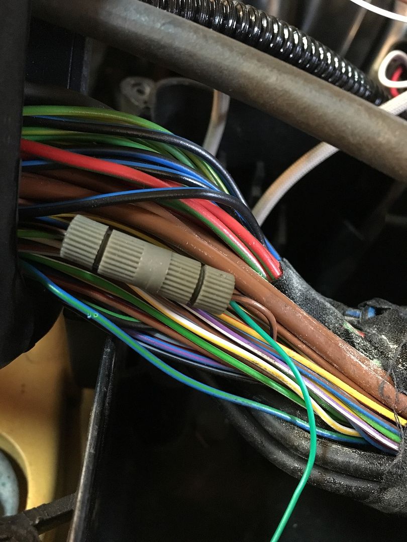
Brown and white wires for the failsafe. Find the Blue with green stripe (ECU pin 104) in the same area of the ECU loom, cut that wire blue/green wire in a convenient place Brown heads off to the N75 direction and White to the ECU direction

That takes care of the all of the connections to the car wiring.
The FAV and flow sensors come out of the ECU box and will bne mounted behind the first fire wall at a later date.

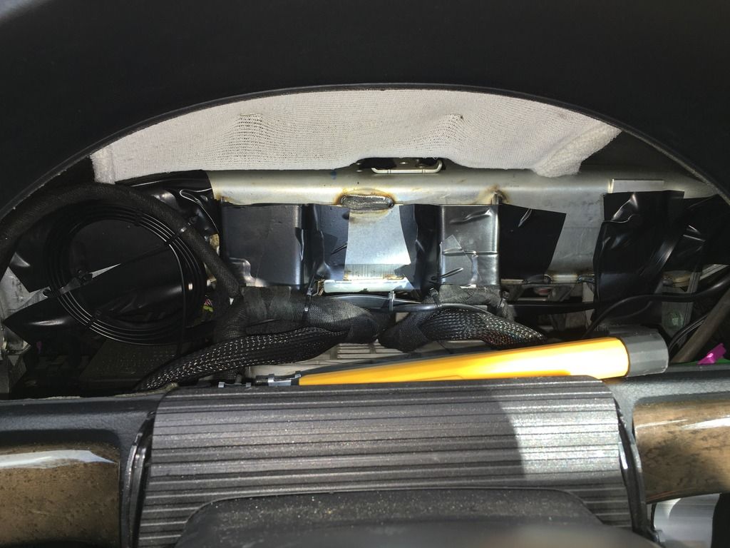
The gauge is pretty self explanatory so I won't go into that, but here's a picture of my routing of the wire behind the cluster. I did cover most exposed metal edges with some really thick wide electrical tape as I've got my Wide-band and Boost gauge wiring in there too.

My requirements for a meth tank were:
-fitting driver side trunk compartment behind the factory cover without looking like a total after though.
-must not have a flat bottom, because that doesn't make sense.
-large capacity, this is a daily driver after all!
-some sort of mounting points.
Here's what I found:
http://www.usplastic.com/catalog/ite...4794&catid=958
I cut the top off to use one of these remote fillers
http://www.usplastic.com/catalog/item.aspx?sku=13871
I chopped off the top and used some tap plastics poly-weld to glue a cover over it because it had a 5" lid!
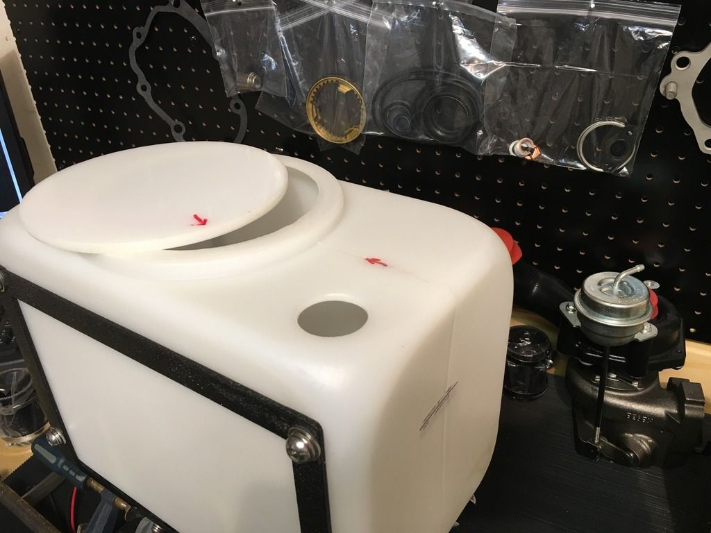
Added some homemade baffling for the hell of it! Don't mind my sloppy fillets it's a bitch to spread nice down that little hole.
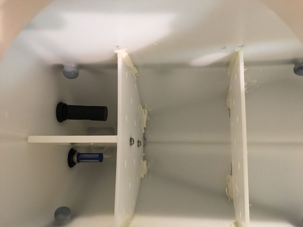
Ill just put up some various pictures of the progress because we all have our different ways of building things, but I did only have to drill one hole for the remote filler bracket. everything else minus the relay and ground for the relay uses a factory threaded mounting point.
Step 1.
Mocked it up with some aluminum before making the final frame out of 1/2"x 1/8" steel bar.
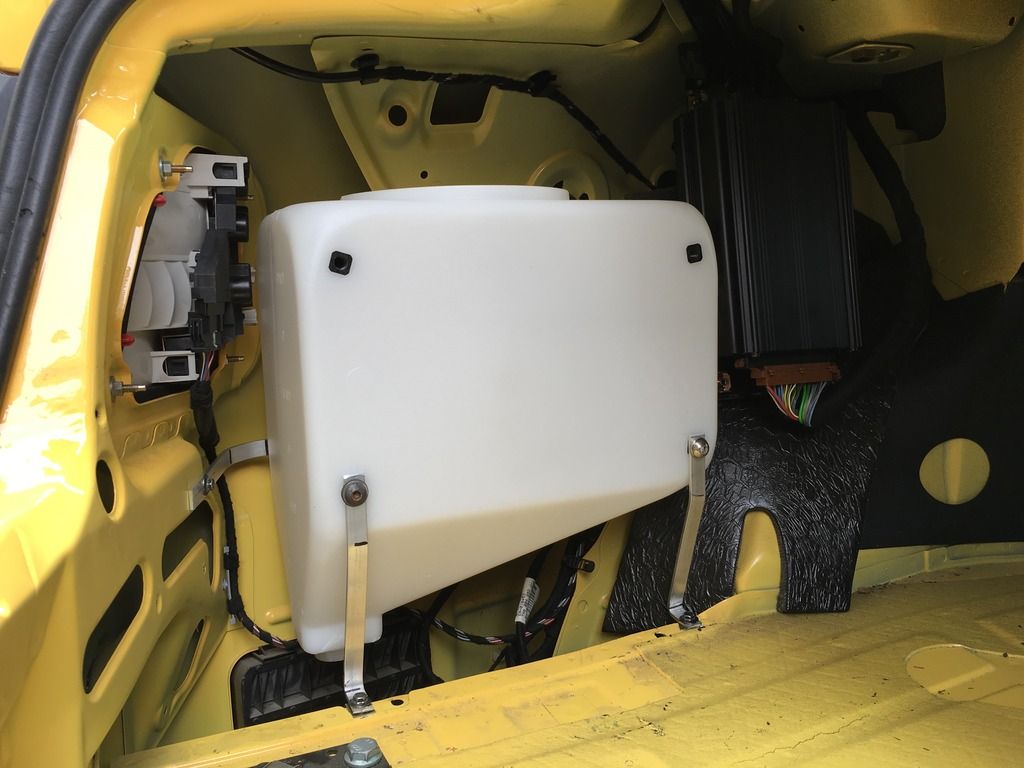
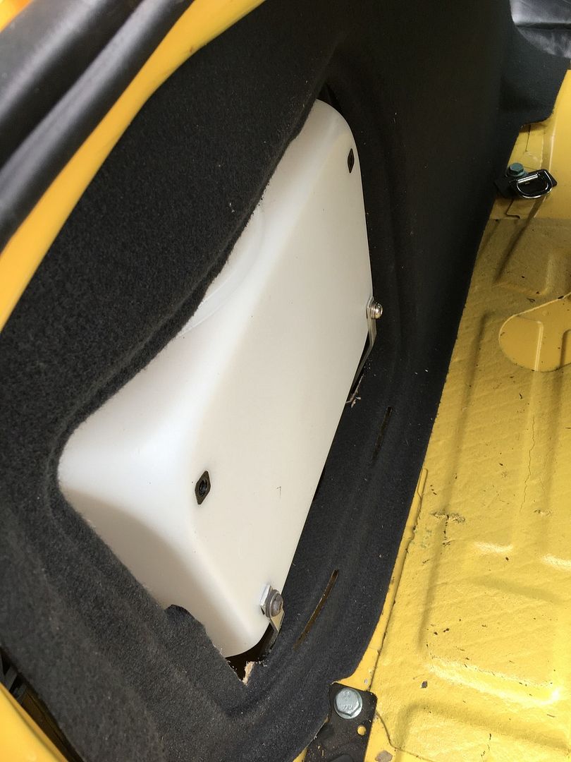
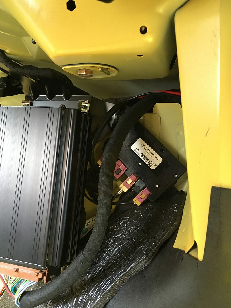
Moved the antenna thingy here.
Step 2.
All of the relay/pump wires were routed along the factory loom that runs from the trunk down the drivers side sill to under the dash.

Step 3.
The frame picks up 3 of 4 of the rear inserts. Painted with my favorite crappy MIG weld cover up, black wrinkle coat. All in all I probably had the meth tank in and out 50 times to get the mounts all nicely lined up so nothing is stressed. I can hand turn every single mounting fastener.

Done!


I not running the meth supply lines till the engine is out for stage 3 things, so those are not covered. Hit me up with any questions.
I hope you have enjoyed my picture fest!!
Justin.


 Reply With Quote

 sold
sold 


Bookmarks