Dismantling and assembling selector mechanism (assembly sequence)
Dismantling – Remove selector mechanism → Chapter
– Shift selector lever into position “N”.
– Remove retaining clips -20- from selector housing -15- and loosen the 4 bolts -17-.
– Lift off frame -9-.
– Shift selector lever to position “D”.
– Pull actuating lever for locking cable -27- upwards out of its bearing and remove actuating lever from selector housing.
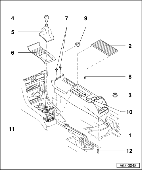
– Pull out locking plates -8- downwards.
NoteThe locking plates -8- have different thicknesses (note installation position and mark accordingly if necessary). The thicker locking plate must be re-installed at the rear.
– Using a screwdriver, press out bearing bushes -7- towards the outside.
– Remove complete selector lever assembly.
– Press out pin -24- for locking pawl -25- towards the inside, using a drift.
– Using a suitable blunt tool, carefully press out solenoid -26- from below through aperture in selector housing.
NoteDo not pull on plug contact. Risk of breakage.
– Carefully lever buffer -11- out of selector housing from outside.
– Drive out both pivot pins -19- for cable lever -13- from inside, using a punch.
– Pull cable lever upwards out of selector housing.
– Detach coupling -14- from cable lever.
– Unclip detent plate -12- from cable lever.
Assembling
Assembly is carried out in reverse sequence; note the following:
– Clip coupling -14- into cable lever -13-.
– Clip detent plate -12- into cable lever -13-.
– Slide cable lever with detent plate into selector housing -15- from above. Ensure correct position when installing (not reversed).
– Drive both pivot pins -19- for cable lever from outside into selector housing as far as stop.
– Push buffer -11- into corresponding mount in selector housing.
– Push selector lever lock solenoid -26- together with locking pawl into selector housing from above.
– Carefully drive in pin -24- for locking pawl -25- from outside.
– Install complete selector lever assembly in selector housing.
– Engage selector lever in cable lever at top and bottom.
– Use a screwdriver to check that the locking pawl is properly engaged when the selector lever is in positions “P” and “N”.
– Push the two bearing bushes -7- for the selector lever into the selector housing from the front and rear respectively. Note ribs in mounting holes.
– Fit locking plates -8- for bearing bushes in selector housing so that their angled ends face inwards.
NoteThe locking plates -8- have different thicknesses (note installation position and mark accordingly if necessary). The thicker locking plate must be re-installed at the rear.
– Shift selector lever to position “D”.
– Fit actuating lever for locking cable in selector housing so you feel it engage in both pivot bearings.
– Shift selector lever into “P” position.
– Check function of actuating lever for locking cable.
l With the selector lever in position“P”, the lever should engage in the detent plate and lock the selector mechanism.
– Fit buffer -23- together with O-ring -22- in shift bearing -21-.
– Push shift bearing -21- all the way onto its seat in the selector housing, starting from the inside.
– Shift selector lever into position “N”.
– Fit frame -9- on selector housing from above and secure using the four bolts -17-.
– Fit retaining clips -20- into selector housing from outside.
– Install selector mechanism → Chapter.


But I woldn't do it if you don't have enough experience. If you know what you are doing, then there you go...


 Reply With Quote


Bookmarks