


This is a project a lot of people have talked about doing over the years. I have had communications with a number of you about this, but no one seemed to have the complete answer as to how to accomplish seat memory and full mirror functionality. I saw this as a personal challenge, a sort of a puzzle, to finally figure this thing out. There were a lot of stops and starts and roadblocks along the way. This took months and months of effort. It was a lot of work, with a lot of study of the Bentley wiring diagrams. I also had a lot of help from Diagnosticator on this. What a great guy and valuable asset here on the forums! Of course, if you have a 3.0 or an S4, you already have all these features.
Background:
Contrary to what's been posted on the forums, there is no VAG-COM solution to this mod. It is also not merely a matter of having the switches, control boxes, etc. What it involves is some re-wiring and building a wire harness where none exists, in addition to the control switches, seat memory module and proper connectors. If you are afraid of doing electrical work on your car, this may not be a mod for you. However, it is fairly straightforward with my DIY and does not require a lot of tools or specialized skills or knowledge. Not even a VAG-COM is required. I am also assuming you know how to remove the door and door sill trim panels, disconnect the battery and such while disconnecting the driver’s seat airbag. These issues have been dealt with in other DIY’s and I will not document with here.
The Seat Memory, Power Fold Mirrors and Right Mirror Tilt functions are interrelated and are dependent upon the CAN Comfort and Convenience Module. CAN stands for Controller Area Network, and there are three distinct CAN networks in our cars. These are; CAN Engine, CAN Infotainment and CAN Comfort and Convenience. It is this last CAN network we are interested in. The CAN busses are bi-directional data exchange networks for various electronic components and control modules in the car. Data is exchanged via the twin wires between the modules and the CAN controller, with unique identifiers for each data packet to allow the control module to know which component it is communicating with. Multiple data packets are sent to and fro over the network at virtually the same time over the two wires, rather than having a discreet wire for data from each component to the controller. This cuts down on the amount of wiring in the car and is a very efficient way to exchange information between the various electronic components in the car. It is essential that you tap into the proper CAN buss for this mod, and not into the other CAN busses controlling the engine and infotainment systems. This CAN system is a pretty cool concept and I am amazed at the engineering genius Audi puts in our cars!
Parts List:
You will need the following bits and pieces to do this mod:
-Power seats with the seat control module. Seats can be regular power seats from a 3.0, S4 Recaro Seats or S-line Seats. These should have the Control Module # 8E0 959 760 on the underside of the driver’s seat. If not, you need to install this module in the seat base.
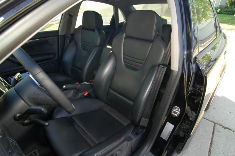
S4 Recaros – best mod ever! Now I have full control over these bad boys!
-S4 or 3.0 power folding mirrors. Don’t have the part numbers for these. I got mine off German ebay as complete units from a Euro S4. These are frequently up for sale on ebay.de. An auto dimming inside rearview mirror is required for the auto dimming function to work on the side mirrors. Mirror folding appears to be a function of the power folding mirrors, 4 position mirror switch, door control module and CAN Comfort and Convenience module. If you merely want mirror folding function, you just need to have these four items and can stop at that. Mirror tilt and memory is a function of the seat memory system, requiring the full mod for that feature, detailed below.
-Four position mirror switch and proper trim piece for door
8E0 959 565 4PK – 4 Position Mirror Control Switch
8E1 867 171 C 7PE – Trim piece for driver’s armrest, to accommodate the above switch
-Proper control modules in the driver and passenger doors
8E1 959 801 – Driver’s side Door Control Module.
8E2 959 802 – Passenger side Door Control Module
Luckily, these were already in my car. Check to make sure you have the right part number, otherwise this mod will not work. Door control modules with the letter “A” following the part number have been reported not to work on the forums.
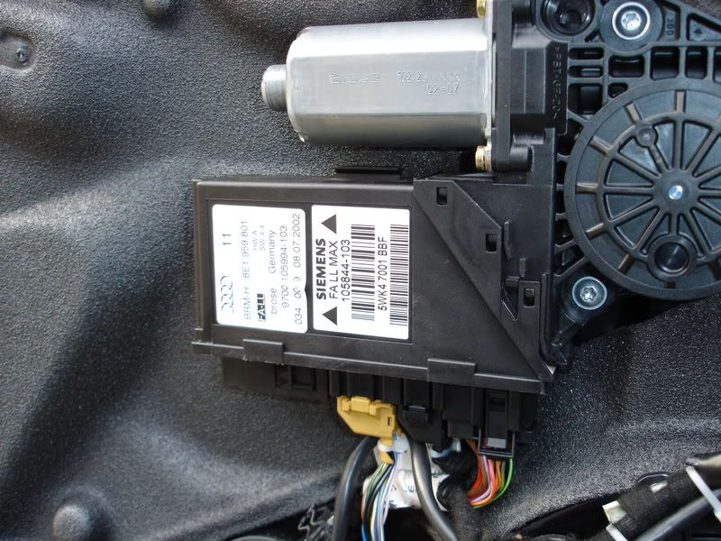
Here is a photo of the driver’s door control module. It is mounted to the door with the window regulator motor.
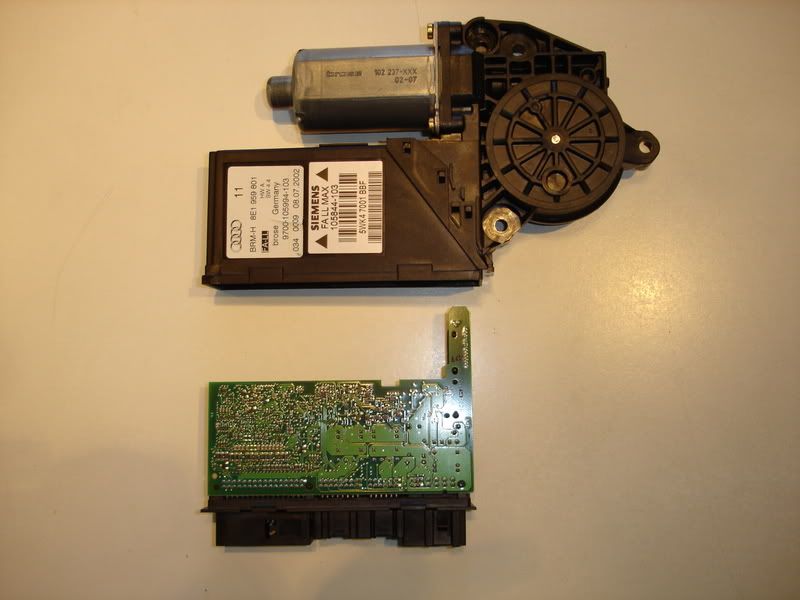
Photo of the electronics removed from the control module

Close up of the door control module electronics. Probably more computing power than the Apollo space capsule had!
-Seat memory control switch in driver's door, with mounting trim piece
8E0 959 769 5PR – Seat Memory Control Switch
8E1 959 527 7PE – Trim piece for above, Soul Black

-Proper plugs and repair wires
9 x 000 979 009 – Repair Wires
2 x 000 979 132 – Repair Wires
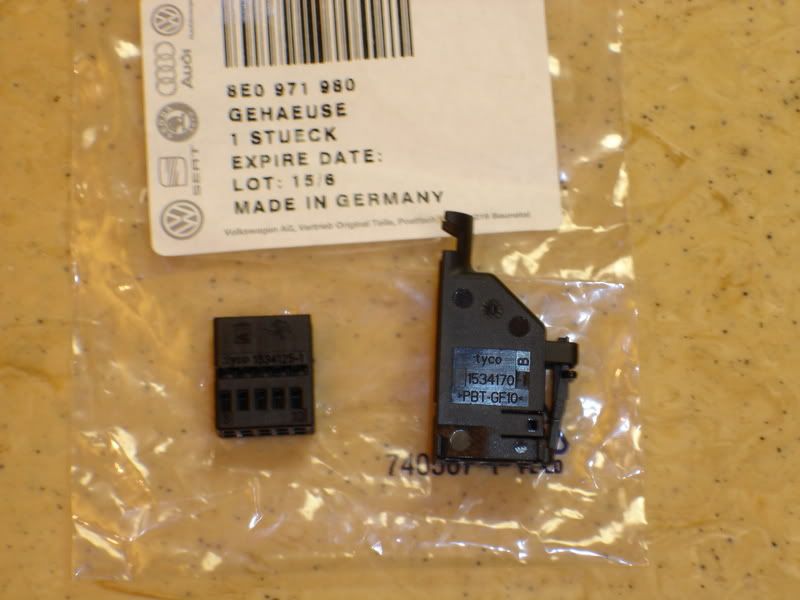
8E0 971 980 – Black 10 pin Plug for Seat Memory Control Switch in door (T10)
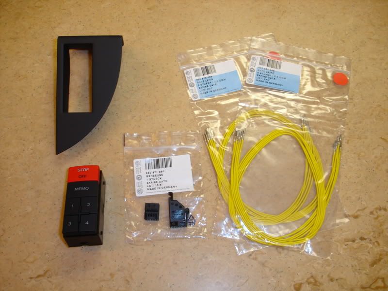
Photo of Memory Control Switch, Mounting Panel, Black 10 Pin Connector and Repair Wires
Misc. Parts Needed:
-3 x Butt Connectors, Red
-5 x Scotch Lock Wire Taps, Red
-Cloth Friction Tape or Spiral Plastic Wire Harness Shield for Wiring Harness
-Several small zip ties
-3 x Approx. 3 ft. lengths of 20-22 AWG wire or CAT 5 wire.
-P-Touch Labeler. I used this to label the wires for the wiring harness. This is very helpful in keeping straight which wire goes where.
-A huge amount of patience studying the Bentley wiring diagrams. Well, I already did this for you! This is what took up lots of hours. That and inventorying the wiring leads in all the harnesses in the door and seat and tracking where they went and what they did. I highly recommend obtaining a Bentley manual for yourself. I have used the Bentley designations for the various components in parentheses if you care to follow along in the manual.
-Some balls to tap into electrical systems in your expensive car!
Tools needed:
-10mm 12 point or Triple Square driver to remove bolts securing driver’s seat. These can be obtained at any auto parts store. ZDMACK.com has a great boxed set of these in 3/8” drive by VIM Tools.
-Torx driver for removing driver’s door armrest, screws located on back of door panel
-10mm socket for disconnecting negative terminal on battery
-Wire Cutter/Stripper
-Crimping tool for butt splices. Most wire strippers will have a crimper on them. These are OK, but a dedicated crimping tool does a much better job. I purchased one from Sears made by GB Tools for about $ 13.00 and it really does a great job.
-Small jeweler’s screwdriver set
-Phillips #2 screwdriver for removing driver’s door panel
-Panel tools for removing the driver’s door panel trim and inner panel. ZDMACK.com sells these.
Procedure:
There are three areas in the car you will be working in. They are as follows:
- Behind the driver’s door panel
- Under the Driver’s Seat, Seat Connector Sockets
- In the Connector Station at the base of the Driver’s A-Pillar
The first thing I did was build the wiring harness needed to go between the Seat Memory Door Control Module and the gray 32 pin connector plug (T32c) which is plugged into the Driver’s Door Control Module (J386). You need to remove the inner door trim panel from the door to gain access to these components (Please refer to Bentley Manual or other DIY for this procedure). At this point, you should verify that your door control module has the proper part number (8E1 959 801), otherwise, you will need to obtain the proper parts to proceed. Upon verifying the control module number, remove the gray 32 pin connector (T32c). You will notice a purple cap on one side of the connector plug. Remove this by sliding it off the plug. Next, clip the zip tie off the plug, taking care to only clip the zip tie and not cut any of the wires in the harness. Slide the inner part of the plug out of its housing.
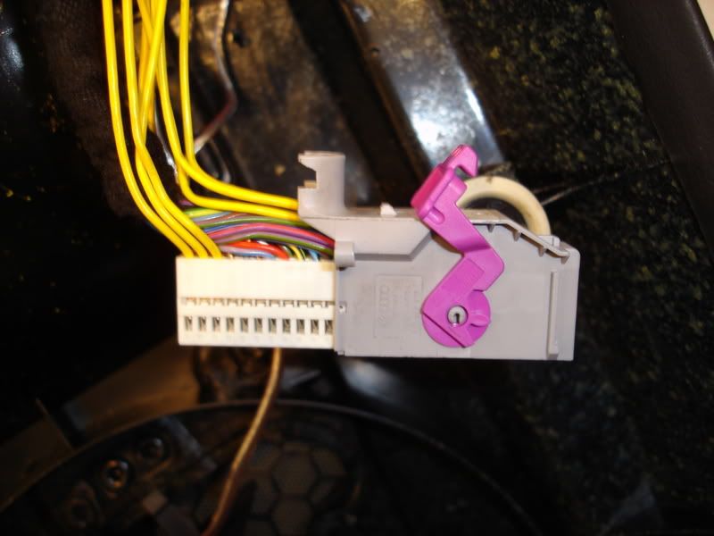
Picture of the gray 32 pin plug (T32c), with inner plug partially removed and repair wires already inserted.
Take note of the numbering sequence on the inner plug. Now, here comes the fun part! You need to add eight of the repair wires (000 979 009) to the gray 32 pin plug. These repair wires consist of a short wire length with the appropriate connectors on both ends. For this part of the harness, do not cut the wires as you will put one end in the T32c plug and the other end into the black 10 pin plug. Insert one end of the repair wire into the designated pin assignment position in T32c. Insert all of the leads into the proper pin holes in gray T32c. Then plug the other ends one by one into black T10.
Close up of black 10 pin plug (T10) separated into its two components.
Here is the order of the connections:
T32c/30>T10/10
T32c/14>T10/9
T32c/19>T10/1
T32c/15>T10/2
T32c/16>T10/7
T32c/17>T10/4
T32c/18>T10/5
T32c/31>T10/8
Take the ten pin connector plug (8E0 971 980) apart and insert the appropriate repair wire end into the proper pin assignment position. Take note that the end of the repair wire must lock into place upon insertion into the plug housing. The repair wire ends have little barbs on them to help them locked into the plug insert. Take care to get this right, or you will have a non-functioning harness on your hands. The repair wire ends are also a real pain to get out if you put them into the wrong pin hole, so take your time. (You can use a jeweler’s screwdriver to push in the locking barb from the side of the plug housing. Just be careful not to damage the pin or the barb.)

Close up of the inner plug component with repair wires inserted.
The pin assignment numbers are really hard to see, but once you make out which hole corresponds to what number, its self explanatory. This is where the P-touch labeler comes into its own.
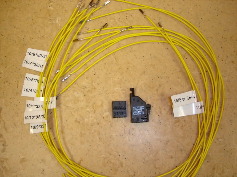
As you can see from the photo, I labeled the repair wires using these labels to help me keep track of the proper order of the repair wire insertion into the plugs. Take your remaining repair wire (000 979 009) and cut it in half. Insert and label it for pin locations 3 and 6 in the black 10 pin plug. Now, re-assemble the gray 32 pin plug by sliding the plug insert back into it’s shell and slide the purple retainer into place to lock it. Tie off the new, bigger bundle of wires with the small zip tie, replacing the zip tie you clipped off. Assemble the black 10 pin connector by sliding the plug insert into its shell until you hear a click when it locks in place. Tie off the wire bundle with a zip tie the same as on the gray 32 pin connector.
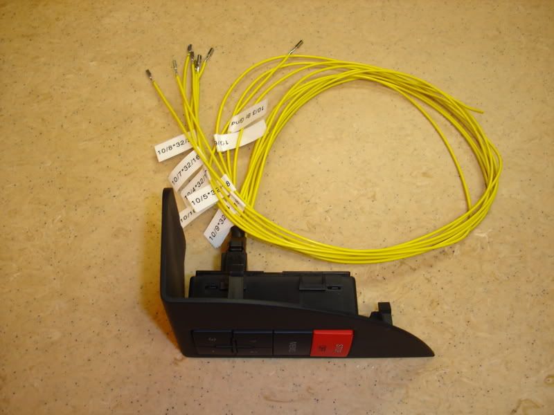
Harness before wrapping, T10 plugged into Memory Control Switch. Note P-touch labels on repair wires.

Harness completed, with repair wires inserted into both plugs, before wrapping.
Wrap the harness in black cloth electrical tape for that OEM look, or use a plastic wire harness wrap like I did. Take care to leave the repair wire leads from T10/3 and T10/6 out of the wrapped harness.
Plug gray T32c back into the door control module. Black plug T10 is then plugged into the Seat Memory Control Switch located in the corner of the driver’s door pocket. You will need to cut away the corner of the door pocket for the control module’s mounting plate. Be careful here! I then secured the switch and mounting plate to the door panel with a hot glue gun. The harness you constructed is more than long enough to bridge this span.

Here’s the finished harness in place on the back of the door card.
Now take the remaining two wires and tap into the brown (br) and blue/brown (bl/br) wires coming from the door lock switch located above the window switches on the door. Tap wire T10/3 into the brown wire and wire T10/6 into the blue/brown wire using the red Scotch Lock taps.

Here’s a close up of where I tapped into the door lock switch wires.
If you are doing the power folding mirrors, you will also need to install the correct mirror switch (8E0 959 565 4PK) and trim panel (8E1 959 527 7PE for Soul/Black)
You will need to remove the driver’s door armrest to do this. The arm rest is secured from the back side of the panel with with Torx screws. Take a look at the photo for the switch and the trim piece with the four mirror positions on it. The lower 6 o’clock position is for the mirror fold. I will not detailing the side mirror install in this DIY.
Insert the four position mirror switch into the trim panel and install the trim panel
into the arm rest. The original plug from the door panel harness is then plugged into
the mirror switch.
You can now re-assemble the door panel to the door. We are done with the most
complicated part of the mod!
Next, you need to remove the driver’s seat. Do this by removing the four 10mm 12 point bolts at the four corners of the seat tracks. See photo for reference.
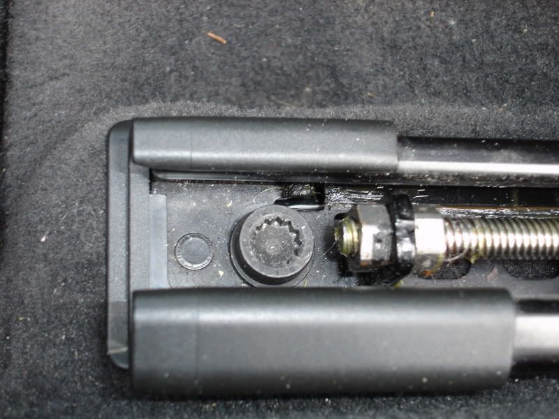
Disconnect the negative terminal from the battery at this point to safely disconnect the airbag in the next step. Use you 10mm socket for this. You don’t have to physically remove the seat from the car, just tilt it back against the rear seat bottom to get it out of the way. While the seat is tipped back, make sure you have the driver’s seat memory module (8E0 959 760) on the underside of the seat. You will see a thick wiring harness coming out of the seat bottom leading to the floor under the seat.
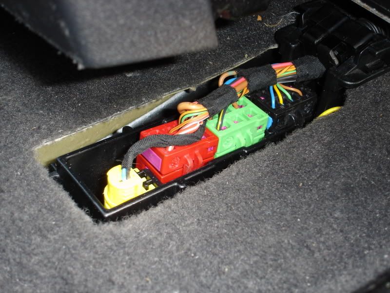
Remove the plastic cover and you will see four connectors; yellow (airbag), red (seat power – the one we will be working on), green (seat heating) and black (seat belt sensors).
Make sure you have disconnected the power at the battery, and then disconnect all four plugs. You will need to get access to the backside of the red socket (T10o) to insert the three repair wires (000 979 132). To do this you will need to release the plug socket from the black frame holding it in place. Use two jeweler’s screwdrivers or picks to release the tabs on both sides of the socket while pushing down on the socket. Push the socket down and to the side and then pull up on it so it is above the level of the carpet. Now it is in a position to work on it.
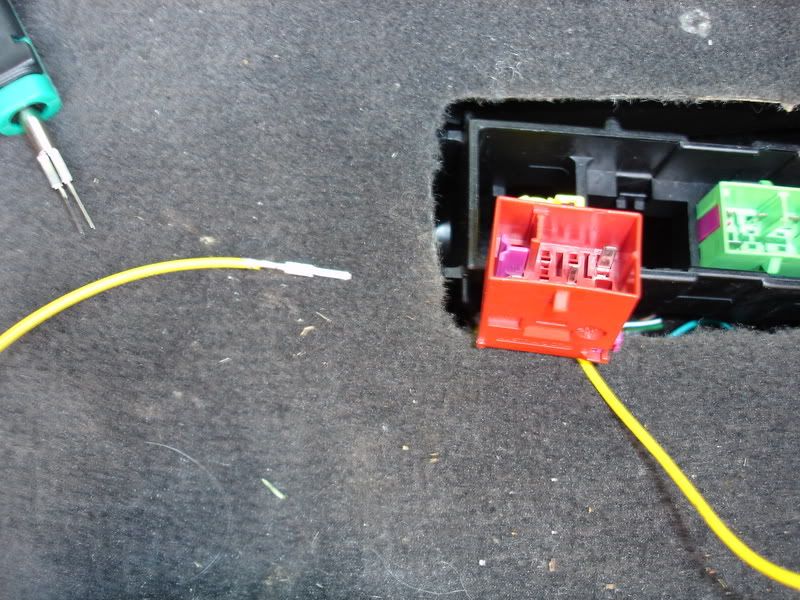
Close up of the socket T10o, with the repair wire 000 979 132 ready to be inserted. Note purple locking tab on the socket.
The red plug socket (T10o) has a purple locking tab that needs to be pulled to insert the repair wires. It is assumed you already have power to the seat, so I will not go into that procedure here. Cut the repair wires in half, so you have three individual wires with the pins on the end. We will be using pin positions T10o/5, T10o/6 and T10o/7. Butt splice your three 3 foot AWG 20-22 wires (some others have suggested CAT 5) to the ends of the repair wires. Insert the repair wire pins into the proper pin assignments from the backside of the socket until you hear them click in place. When you have all three in place, slide the purple locking tab back into place to lock the repair wires and re-install the red plug socket into the black frame in the floor. Plug in the four plugs from the seat harness back into the floor sockets. Run the wires you just installed in the socket under the carpet to the connection station in the driver’s A-pillar.
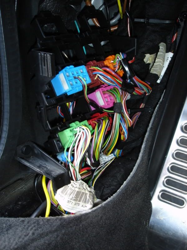
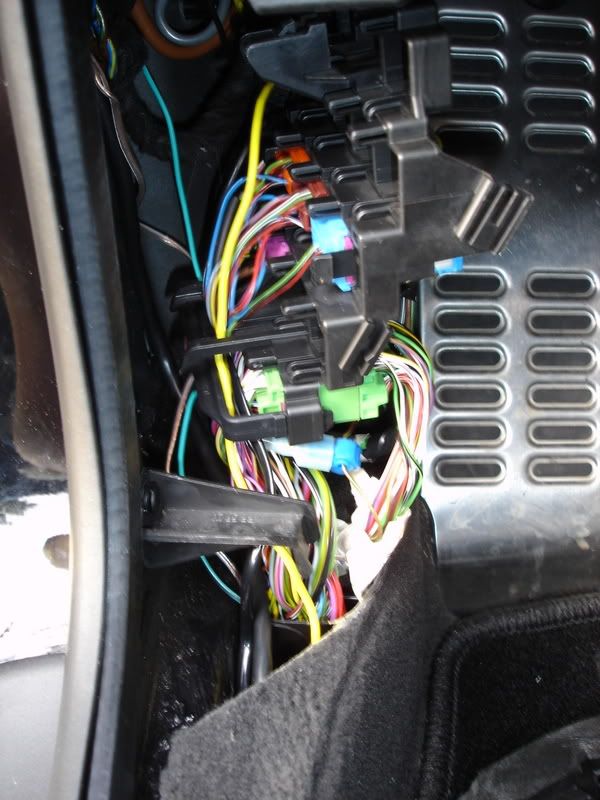
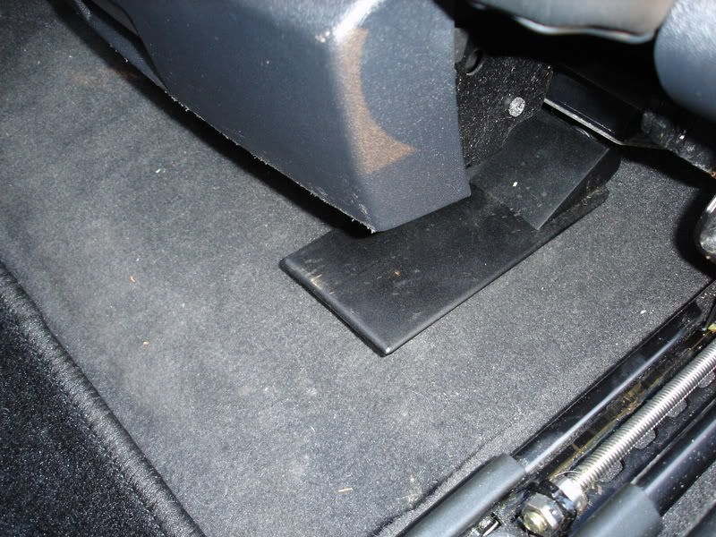
You will need to move the connection station aside to get to the wire harness with the CAN High and Low wires.
Here is where the harness is routed through the pillar. Note the green wire running to the green/black wire.
You will now need to tap the other end of these wires into the three wires located in the driver’s side A-pillar area, behind the connection station. If you look closely at the photos below, you will see I tapped into the CAN wires on the inner side of the A-pillar and the green/black inside the bellows coupling between the outside of the A-pillar and the driver’s door itself. The wiring order is as follows; T10o/6 to orange/green (or/gn) for CAN Comfort High, T10o/7 to orange/brown (or/br) for CAN Comfort Low and T10o/5 to green/black (gn/sw). If you reach up inside the A-pillar behind the connection station, you will find a thick wiring harness. I pulled this down and carefully cut away some of the tape covering. You will find the two CAN wires here. I could not find the green/black wire in this harness, but I did find it in the bellows coupling between the door and A-pillar, so I tapped into it there.
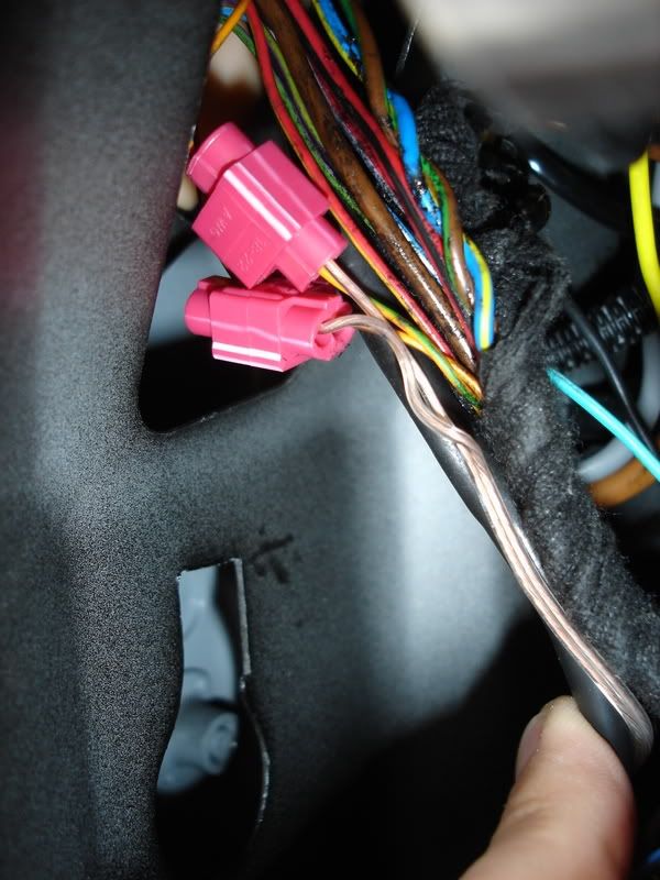
Location of the two CAN wires I tapped on the inside of the A-pillar. Notice how this this wire harness is. It comes out of the A-pillar and heads on up to the instrument panel. Carefully cut away some of the cloth tape wrapping to access the CAN wires here.
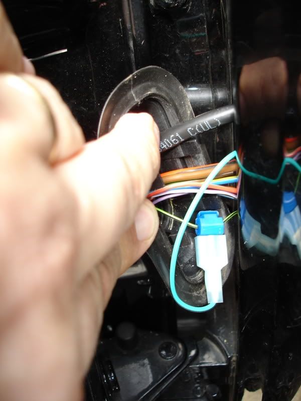
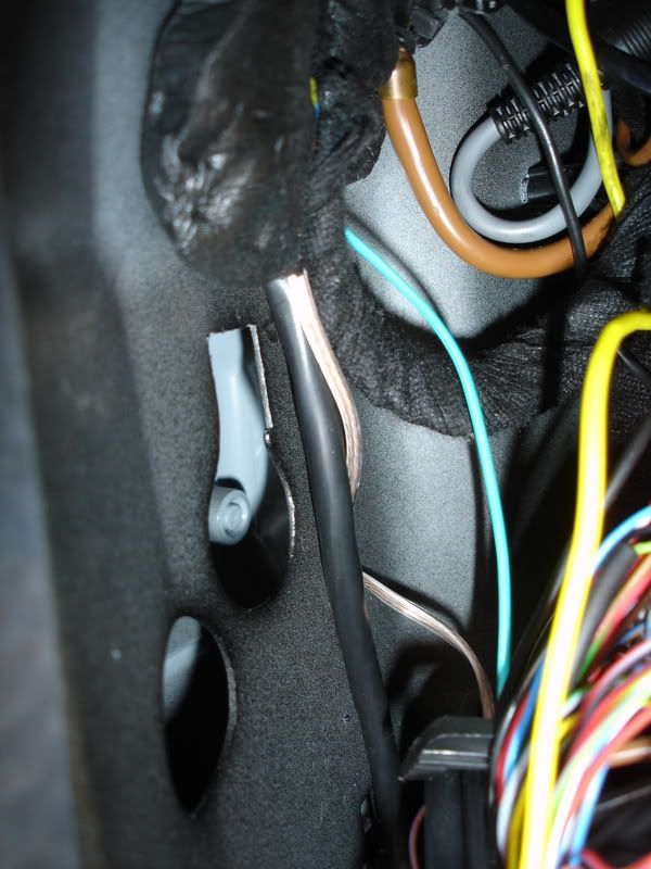
Green/black wire tap in the bellows coupling.
Not as elegant as I would have liked, but it worked! You can now re-install the seat and trim panels on the driver’s side door sill. Re-connect the negative battery terminal.
Everything should be working at this point. It was really cool to see the mirror tilt down in reverse and the seat going back to its memorized position. You need to put the mirror switch in the right hand position for the tilt function to work. Mirrors fold with the switch in the 6 o’clock position. Please look up the seat memory programming procedure in your owner’s manual.
Hope you have fun doing this mod now that I have done all the leg work for you.


Bookmarks