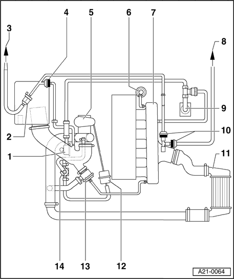
KEY TO DIAGRAM ABOVE for AWM motor
Connection diagram for charge air control and vacuum pressure control
1 - to EVAP canister
2 - EVAP Canister Purge Regulator valve -N80-
3 - Non-return valve for EVAP canister
Between EVAP canister and intake line in front of exhaust turbocharger
Note position (light side/ dark side) as shown in Fig; arrow faces in direction of flow
4 - Air cleaner
With Mass Air Flow (MAF) sensor -G70-
5 - Turbocharger
Check charge pressure Page 21-8
6 - Combination valve for secondary air injection
7 - Fuel pressure regulator
8 - To brake servo
9 - Non-return valve
Between brake servo and intake line
Note position (light side/ dark side) as shown in Fig; arrow faces in direction of flow
10 - Suction jet pump
11 - Non-return valve
Between brake servo and intake line
Note position (light side/ dark side) as shown in Fig; arrow faces in direction of flow
12 - Vacuum reservoir
Location: In front left wheel housing beneath wheel housing liner
13 - Secondary Air Injection (AIR) Solenoid valve -N112-
Location: Below intake line
14 - Crankcase breather
15 - Non-return valve
Between EVAP canister and intake line
Note position (light side/ dark side) as shown in Fig; arrow faces in direction of flow
16 - From Leak Detection Pump (LDP) -V144-
17 - Charge air cooler
With Charge Air Pressure sensor -G31-
18 - Throttle Valve Control Module -J338-
19 - Recirculating valve for turbocharger -N249-
Location: below intake line
20 - Intake manifold
With Intake Air Temperature (IAT) sensor -G42-
21 - Vacuum unit for charge pressure control
22 - Wastegate Bypass Regulator valve -N75-
Checking Page 21-33
23 - Mechanical air recirculation valve
Checking Page 21-24
24 - Crankcase breather pressure regulating valve
25 - Secondary Air Injection (AIR) Pump motor -V101-
Charge air regulation, overview for engine code AEB
Vehicles with manual transmission
1 - Pressure regulator valve
For crankcase ventilation
2 - Evaporative Emission (EVAP) canister purge regulator valve -N80-
3 - To Evaporative Emission (EVAP) canister
4 - Check valve for Evaporative Emission (EVAP) canister
Installed position (light/dark): as shown in illustration
5 - Turbocharger
6 - Fuel pressure regulator
7 - Intake manifold
8 - To Leak Detection Pump (LDP) -V144-
9 - Crankcase ventilation
10 - Check valve for Evaporative Emission (EVAP) canister
Installed position (light/dark): as shown in illustration
11 - Charge air cooler
12 - Pressure unit
For wastegate
13 - Charge pressure bypass valve
Checking Page 21-11
14 - Wastegate bypass regulator valve -N75-

Charge air regulation / secondary air vacuum control, overview for engine code ATW
1 - EVAP canister
2 - From fuel tank
3 - Evaporative Emission (EVAP) canister purge regulator valve -N80-
4 - Check-valve for EVAP canister
Between EVAP canister and intake manifold before turbocharger
Installation position (light/dark side): Arrow points in direction of flow, as shown
5 - Air cleaner
6 - Turbocharger
Check charge air pressure Page 21-51
7 - Combination valve for secondary air injection
8 - Fuel pressure regulator
9 - To power brake booster
10 - Check valve
Installation position (light/dark side): Arrow points in direction of flow, as shown
11 - Vacuum booster
12 - To Leak Detection Pump (LDP)
13 - Vacuum reservoir
14 - Distributor piece
15 - Check valve
Installation position (light/dark side): Arrow points in direction of flow, as shown
16 - Secondary Air Injection (AIR) solenoid valve -N112-
17 - Crankcase vent
18 - Check valve
Installation position (light/dark side): Arrow points in direction of flow, as shown
19 - To tank Leak Detection Pump (LDP) -V144-
20 - Check valve
Installation position (light/dark side): Arrow points in direction of flow, as shown
21 - Charge air cooler
With charge air pressure sensor -G31-
Checking -G31- Page 21-63
22 - Throttle valve control module -J338-
23 - Recirculating valve for turbocharger -N249-
Checking Page 21-45
24 - Intake manifold
With Intake Air Temperature (IAT) sensor -G42-
25 - Pressure unit
For wastegate
26 - Wastegate bypass regulator valve -N75-
Checking Page 21-57
27 - Mechanical recirculation valve
Checking Page 21-43
28 - Pressure control valve for crankcase ventilation
29 - Secondary Air Injection (AIR) pump motor -V101-


1.8TQT (SOLD)

Natasha: 01 A4 2.0 T28/T04 || Silver (Fastest Color)

Bookmarks