


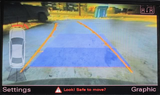
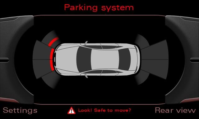
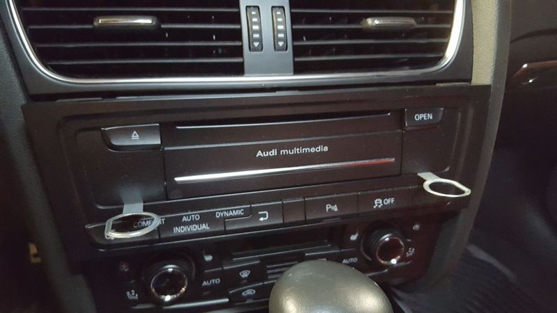
Purpose: Retrofit front parking sensors, upgrade from APS (rear parking and camera only) to APS+ (front and rear sensors). Two additional benefits from this retrofit: (1) you can turn on the parking sensors without having to shift into reverse and (2) you can see which parking sensor is going off and how close an object is to EACH parking sensor. Here are the two new interfaces:
Disclaimer: I am not responsible for any damages that occur to you or your vehicle. This guide is just here to help explain the steps taken to retrofit the APS+ system. Additionally, I hadnt originally intended on putting together a DIY, so I didnt take as many photos as I would have liked. Therefore, you may see some different car exterior and interior colors. The colors may change, but the steps are sequential and in the correct order. For steps where I didnt have any pictures available to me, I took additional photos of my own car to try to bridge those gaps.
Note about Parts:
All OEM parts were used for this retrofit. These can be found in various places on the internet. The only thing that was not OEM was the wiring harnesses, since Audi doesnt sell them. I sourced mine from Kufatec. I highly recommend going through Alex@Europrice; he was knowledgeable and very easy to deal with.
Application to your specific car:
Depending on which combination of options and year your car is, the retrofit will be slightly different. Through my research I have come across a lot of the issues others have faced that I may or may not have had to deal with for my car. For reference, my car, for which this guide is based on, is a North American B8 S4 with navigation/rear parking sensors and without side assist. This guide is generally applicable to B8 and B5.5 A4/S4/A5/S5/Q5/SQ5, with minimal variation. Different markets may have some things switched around (i.e. RHD cars have components in different locations and different equipment levels). Below are some of the complications when retrofitting this system for certain years and/or equipment levels:
1) B8.5 (2013-2016) cars: They do not have a dedicated module for the parking system (it is part of the central electronics module), so retrofitting front parking sensors isnt the same as it is with the B8, which does have a dedicated module for it. For B8.5 cars, the easiest route is to add the B8s 8 channel parking module. I believe the additional steps involve wiring the system to the cars CANBUS and I have read that you may need to get the dealer to activate the new parking module in the car. It has been discussed at length here: http://www.audizine.com/forum/showth...lift-2013-B8-5
2) B8/B8.5 cars without navigation/rear parking sensors: If your car doesnt have the navigation package (which includes rear parking sensors), then retrofitting all 8 sensors is possible, but requires more work and some additional hardware. You also have a bit of a different installation, since the parking buttons are on the center console below the shifter rather than the dashboard.
3) Audi Side Assist: if your car has side assist (blindspot monitoring), there is an additional wire that needs to be added to the control unit harness for everything to work correctly. I am not sure on the specifics, since my car doesnt have side assist.
Tools Needed:
Flathead screw driver
Plastic Pry bars
Drill and drill bits
Metric Step Drill Bit
Painters Tape
Radio Removal Keys
Wire Terminal Removal Tool (you can use jewelry screwdrivers instead, but these are much easier and quicker)
Rod to help feed the wiring through the car
VAGCOM for coding
Parts Needed (including OEM Part Numbers where applicable):
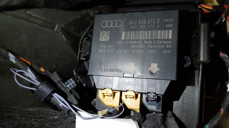
8 Channel Parking Module (these part numbers are interchangeable): 8K0919475J, 8K0919475R, 8K0919475AA
Kufatec Wiring Harness 36316 (Control Unit harness)
Kufatec Wiring harness 36318 (front PDC harness)
2 PDC Sensors for the bumper (need to get these painted your bumpers color): 1S0919275C
2 PDC Sensors for the grille (these come black, so you may need to get these painted to match your grille): 1S0919275D
Note: I actually used all 4 of the C version in my install. If I were to do it again, I would get the D version, which would hide the plug from view better after installed. They are interchangeable in functionality, but the C versions plug is straight down from the sensor while the D version bends the plug 90 degrees.
4 PDC Sensor O Rings: 3C0919659
2 Bumper PDC Brackets: Audi doesnt actually sell these individually. Through my research, others have successfully used VW B6 Passat PDC bracket. They are curved and match the curvature of the Audi B8 bumper. I used them and havent had any issues with fitment: VW Part Number 3C5919491M
2 Grille PDC Brackets: Depending on which grille you have, these will differ. OEM grilles have either brackets that clip into slats in the grille or you need to get a new front plate mount or filler that has 2 holes for PDCs. If you are getting/have an aftermarket RS4 style grille like I do, make sure it comes with the PDC brackets that clip into one of the hexagons.
2 PDC Sensor Tape (I just used 3M tape and cut it, but VW does sell pre-cut tape): 3C0919939A
Dash Switch: For LHD cars with the ESP switch on the right side of the dash and no rear sunshade. 8K2959674GV10. There are a lot of variations of this button assembly (rear sunshade, RHD version, non-navigation version, etc.).
Buzzer: 8E0919279
Rivets for Buzzer: 7L6868307
Zip ties (I used Velcro ties, but either will work)
Before Beginning:
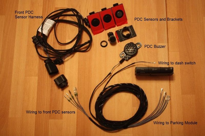
I pre-assembled as much as I could and I recommend doing this as well. I labeled all of the wires with the slot numbers they will go in, which will make sure all the plugs were wired correctly. Kufatec prints the numbers on all of their wiring with numbers that correspond with the correct slots in the plugs, but it is tough to read. I labeled them before installing to make it much easier for myself and I recommend you do the same. Note: Do NOT pre-assemble the end of the Control Unit harness that connects to the front PDC harness because this needs to be done AFTER installing the wiring in the car (see step 14 for why you need to do this). Just tape these wires together to make it easier to feed through the interior trim. Here is a picture of the wiring harness for your reference.
Step 1: Pull Down the trunk panel on the passenger side of your trunk to expose the parking module.
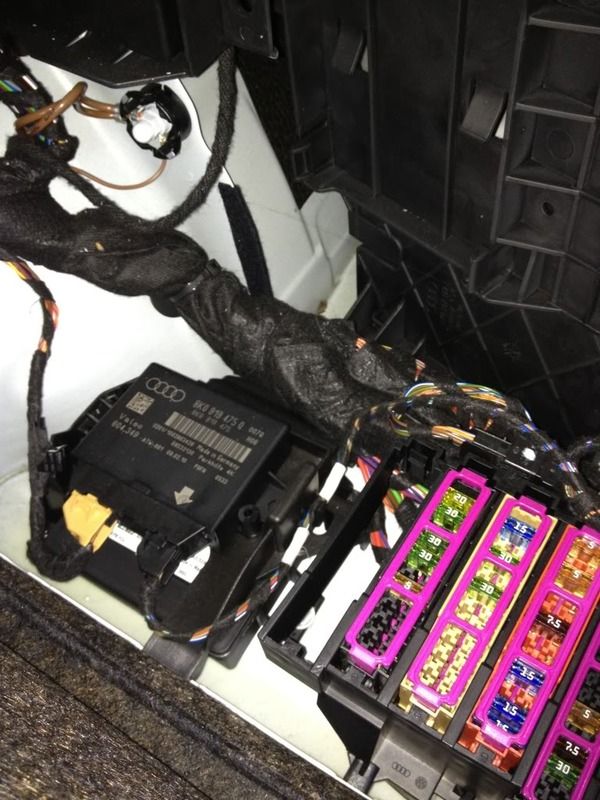
Step 2: remove the old 4 channel parking module and unplug the 2 harnesses. It is clipped into a plastic piece and can be released without any tools. Just push on the clip on the right and it will release.
Step 3: On the leftmost beige plug, youll need to remove the jacket to expose the wiring. For help on removing terminals and wiring, etc. see this video: https://www.youtube.com/watch?v=5rlXZUvhEsQ
On the new harness youve purchased, the end that goes to the Parking Module has 2 wires that are separate from the others (hard to see in pictures). The separate 2 wires plug into their corresponding numbers in the factory plug you took apart (the numbers are in all 4 corners of the plug and you can count to the slots you need this is true for all of the plugs you will encounter). They plug into terminals 4 and 13 on the existing plug. Then, put the jacket back on the harness.
Step 4: install the 8 channel parking module, plug the rear parking sensor plug back into the rightmost slot, the new front control unit harness to the middle (the remaining loose wires are installed into a new plug that should be provided when buying the harness), and the existing (with newly integrated 2 wires) main harness to the leftmost plug.
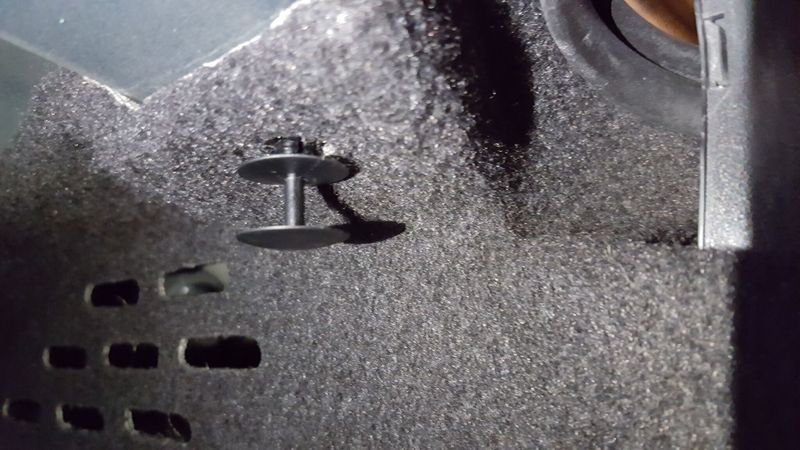
Step 5: pull your rear passenger side seat passthrough down. Look at the top of the inside of the trunk and there are 2 rivets (they look like round plastic dots) on the passenger side that need to be removed from the trunk liner in order to run the wiring to the rest of the car. Remove the rivets with the flathead screw driver and set aside for reinstallation at the end. One is towards the back of the car and the other is towards the front. Then pull the carpeting away from the passenger side so you can fit your hands through to run the wiring. I followed the existing harness already in the trunk. String the harness over the rear wheel hub and out towards the backseat. You should pull it through to the cabin by going between the rear air bag in the back seat trim.
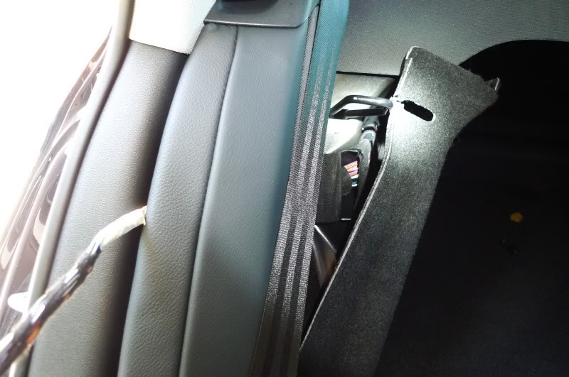
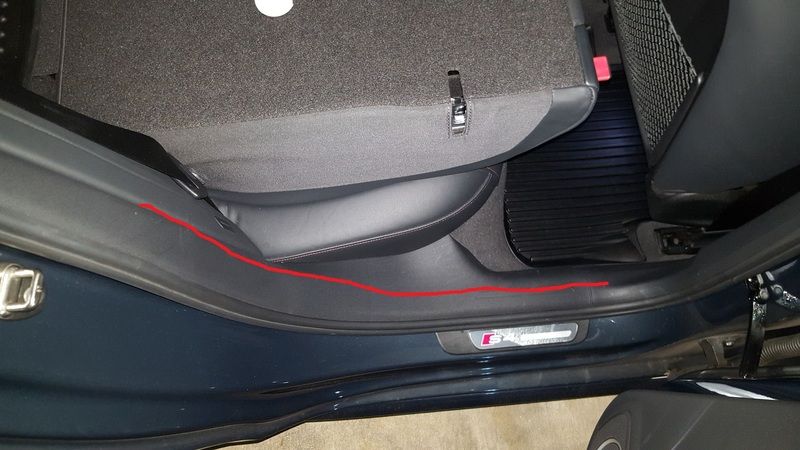
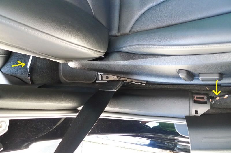
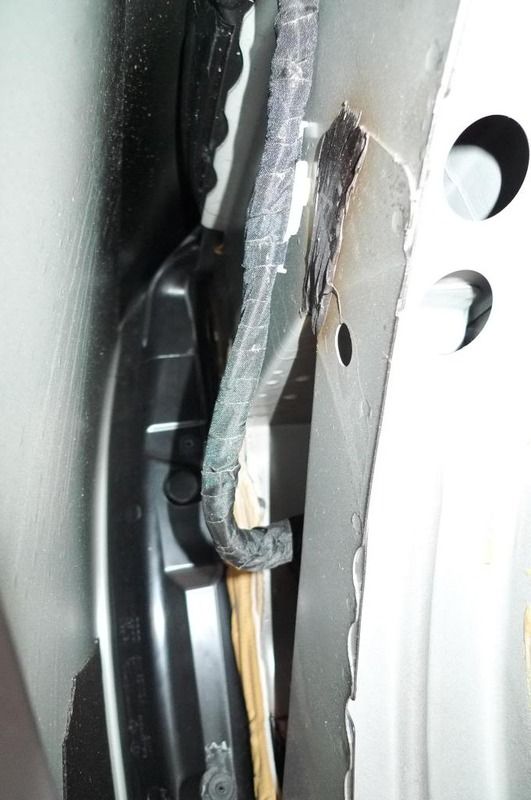
Step 6: You will run the wiring down the rear seat trim next to the door and it will be wired through to the front of the interior cabin. It will follow the red line in the picture below.
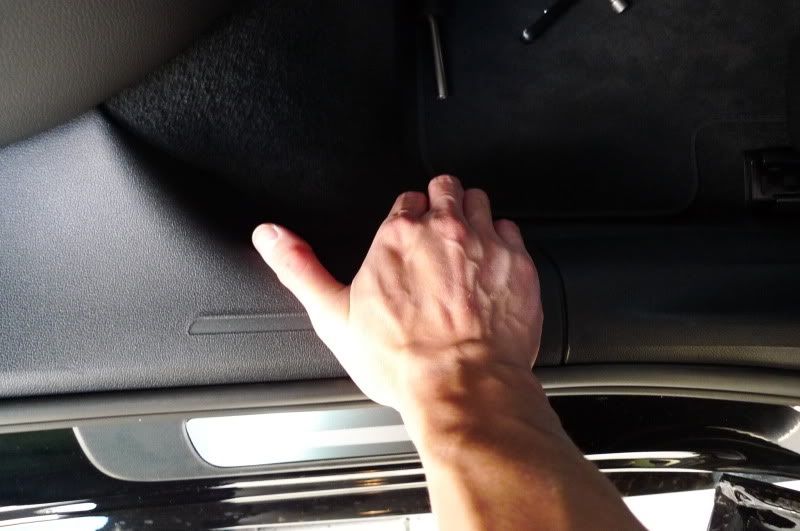
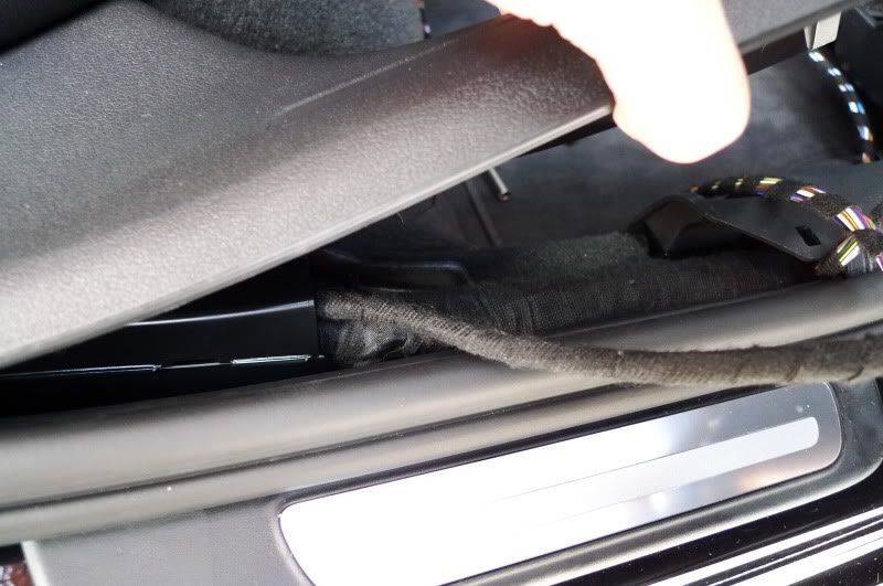
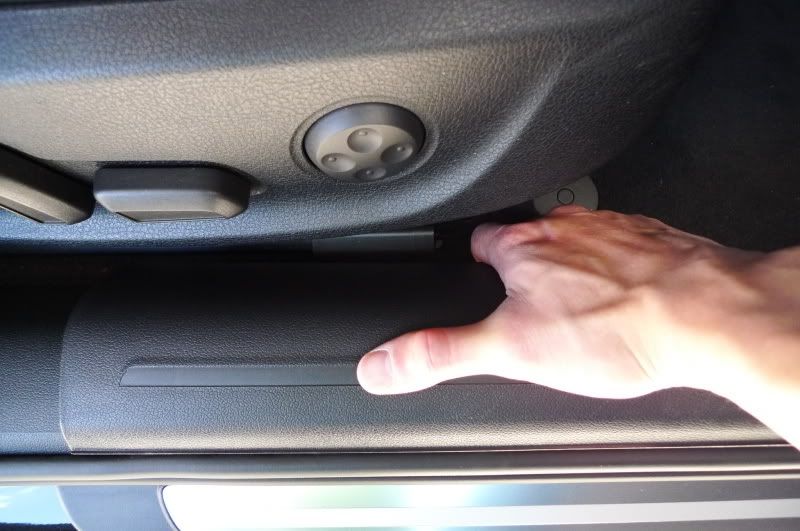
Step 7: Remove the passenger front and rear interior kick panel to expose the existing wiring. There arent any screws, you just pull straight up and you will remove it from the clips that hold it in place (you have to pull with a good amount of force). The front should be removed; the rear just needs to be loosened. Youll follow this wiring all the way to the glove box area. I used the rod to feed the wiring through since it wont go through on its own. I taped the harness to the rod and fed it through to the front seats. (if anyone has ran wiring behind a wall in your house/apt, it is the same concept). Keep feeding the wiring through from the back seat to the front until you do see it. Grab it and pull all the wiring through to the front seat footwell.

Step 8: Remove the glovebox. It is held together with 8mm bolts (I forget how many, but it was a lot). For help removing the glovebox, see the video here: https://www.youtube.com/watch?v=umwUwoumETs
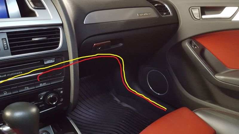
The buzzer and dash button wiring will go behind the glovebox. See the picture below; the red line is the dash button wiring and the yellow is the buzzer wiring. The buzzer wiring will end up behind the cage for the radio.
Step 9: Remove the radio using the radio keys (If you have an auto, youll need to shift the car into neutral/drive to get the radio out).
Step 10: Run the part of the harness for the buzzer and dash button across to the radio cage. The 2 lose wires go to the dash button, the 2 wire plug goes to the buzzer. Remove the original ESP only switch from the radio by releasing the two tabs that keep it in place (can use a small screwdriver for this). It will just pop out. Unplug the harness, set aside the old dash switch and grab the new one with the parking button on it. Before plugging it in, you need to remove the jacket and integrate the two new lose wires into that plug. You do this the same way you did for the plug in the trunk (see step 3). Add these 2 lose wires to terminals 1 and 3. After doing this, plug the integrated harness into the new switch and you can clip it back onto the rest of the MMI radio.
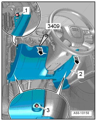
Step 11: Before putting the radio back, run the buzzer plug behind the radio harness to the drivers side. To do this, youll need to remove the drivers side lower dash panel. Go to the drivers side of the car, remove the fuse panel cover (use a flathead screw driver on the cutout and pull to release the 3 clips). Then you will see a hidden bolt that can be removed with a 8mm socket. There are also 2 other 8mm bolts that are exposed towards the bottom of the panel (where your feet normally go when driving). Remove all 3 bolts and youll have to pull the entire panel down to remove it. The left side is pretty easy, the right side takes a good amount of force. The picture below shows visually how to do it.
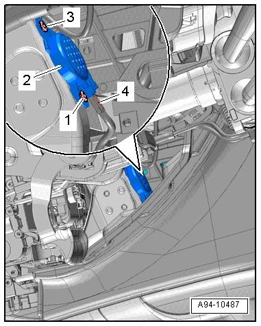
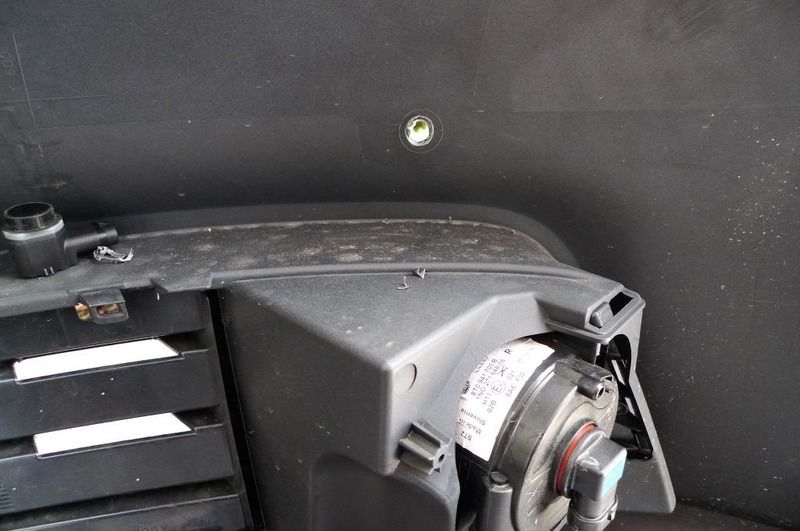
Step 12: Feed the buzzer harness across to the drivers side and then grab the buzzer. To install it is a HUGE pain, probably the hardest part of this install. The area is tight and if you drop the buzzer rivets, theyre gone forever. Behind the radio cage (you are looking at it from the drivers side), there is a metal bracket with 2 holes where the rivets go. Push the rivets through the buzzer holes and into the bracket and tighten. Dont forget to plug the buzzer into the harness. The picture below should help you understand what I am talking about.
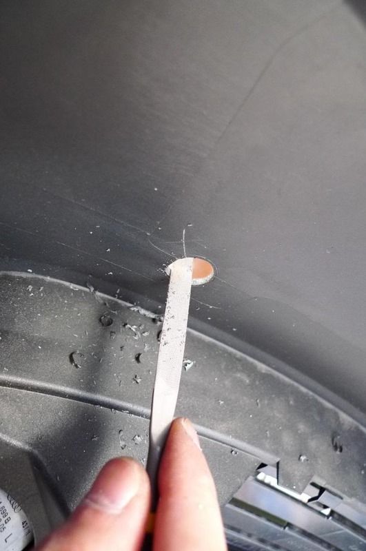
Step 13: Once that is done and everything in the dash area is plugged in, go back to the passenger side footwell. Reinstall the glove box so you can put yourself in the passenger footwell area. With the interior kick panel still off you will see all of the exposed wiring and modules. If you look up (looking towards the door/fender of the car) you will see a black grommet about 2 inches in diameter with a big wiring harness going through it. Here is where youll feed the remainder of your control unit wiring harness through.
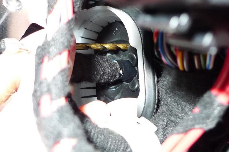
Step 14: Remember when I told you not to assemble the part of the harness that connects the front PDC harness to the control unit harness? This step is why. Youll need to use your drill to drill a hole in the black grommet (the existing hole is sealed tight) large enough to start feeding wires through. After drilling the hole, feed the wiring through the hole. Try to make the hole as small as possible since it will seal better from the elements this way. The one I made would barely fit the harness through, which is what you want.
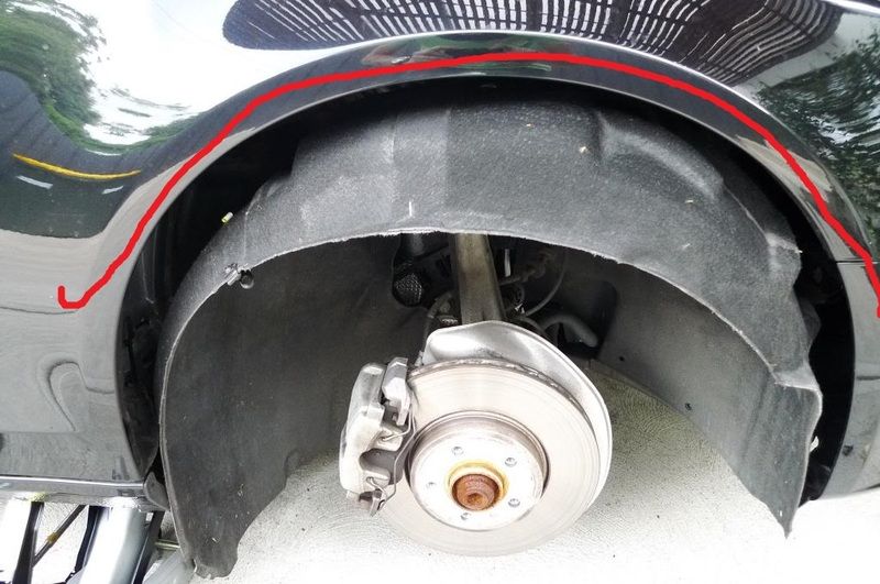
Step 15: Jack the car up and remove the wheel well liner. It is a series of bolts and clips that can be a pain. For direction on how to remove those, see the link to the DIY to remove the front bumper in step 17.
Step 16: with the wheel well liner removed, look behind the fender and you should be able to see the wiring harness you fed through the black grommet. If not, you can reach back there and grab it. Pull what remains of the slack through the grommet and out the wheel well.
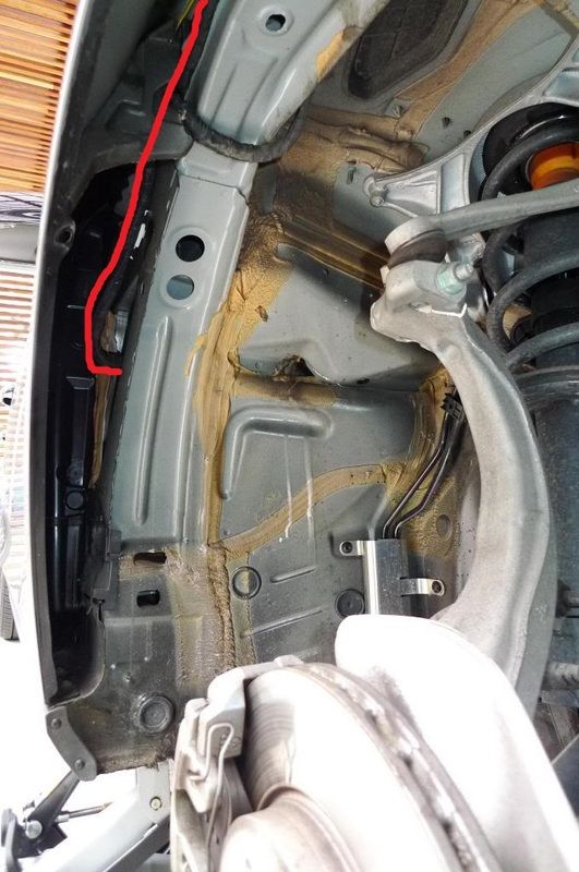
Here is the view if you are looking in the wheel well towards the back of the car. This is where the wiring you passed through the black grommet ends up. Again, red lines show where the new wiring that youre adding are ran.
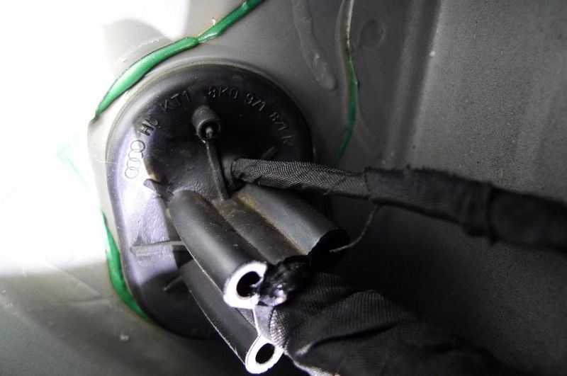
Here is a closeup of the inside of the fender, where the wiring from inside the cabin ends up.
Step 17: Remove the front bumper and set it aside. See this DIY to remove it: http://www.audizine.com/forum/showth...lacement-Guide
Step 18: Run the wiring along the existing wiring (again, use cable ties/Velcro ties to secure it to existing harnesses in the car). Run your harness up and around the wheel well and it will end up below the passenger side headlight. The red lines I added to the picture show how the wiring is ran from the black grommet, behind the fender, and around the wheel well.
Step 19: With the front bumper removed, you need to drill two 18mm holes into the front bumper. I consulted with my friend who works at a body shop on how to best drill without ruining the paint and he recommended using a step drill and a file (I have seen this recommended in a few other places as well). He also recommended putting a few layers of painters tape on the painted side of the bumper before drilling to protect the paint from tearing. The PDC sensor locations are pre-marked on the back of the OEM bumper, so where to drill isnt an issue. I recommend using a little bit of touchup paint to color match the inside of the holes you just created.
Note about the grille: I went with an aftermarket RS4 style grille, which came with 2 brackets for the PDC sensors. If you want to reuse the OEM grille, you can, but youll need the OEM brackets for them. I believe these just clip onto the OEM grille. Whichever route you go, remember you will need these brackets to clip into the grille.
Step 20: Attach the PDC sensor brackets to the grille and bumper using the PDC sensor tape (or 3M equivalent). For the bumper brackets, I first installed the PDC sensors into the brackets, then stuck them onto the bumper. Also attach the grille brackets. Note: all of the PDC sensors should have the plugs facing the passenger side (so the harness has more slack). Also, dont forget the o ring for each sensor!
Step 21: Going back to the Control Unit harness (if youve followed my instructions, it should be sitting below your passenger headlight), now you should insert the pins into the connector to get ready to plug the front PDC harness into it (here is where labelling all of the wires pays off). Once these are all plugged in and the retainer clip for the plug is inserted, grab your front PDC harness and plug in all 4 PDC sensors and connect it to the Control Unit harness.
Note: It is a good idea to check the entire system to make sure everything works properly (this will be the first time everything is physically connected in the car. In this case, skip down to Step 24 to do the VAGCOM coding so you can test it.
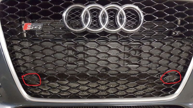
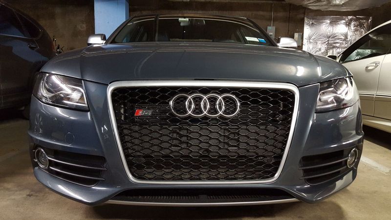
Step 22: Tidy up wiring. I made sure throughout the car that the wiring all followed the factory harnesses so that nothing would get pinched or snagged when reassembling the interior panels (you can do this incrementally or all at the end). I reused the OEM Styrofoam piece behind the center of the grille. This has cutouts for the wiring to be snaked through (anyone who has ever taken their bumper off probably knows what I am referring to) so I wanted to keep that intact. Since I have a RS4 style grille, I had to shave down the OEM piece to make the bumper fit properly. This took a bit of extra work, but makes it look much cleaner in the end, hides the wiring, and also keeps it from being exposed to the elements when driving. Here is what the grille looks like with the wiring done and the PDC sensors installed:
Step 23: Reinstall everything: front bumper, interior trim pieces, radio, lower dash panel, trunk lining, whatever is left that was taken apart in this install.
The final product:
Step 24: Youll need to code the car to recognize that youve now installed the APS+ system.
Activate APS+: Go to 10 - Parking Aid, 8 - Coding, Byte 0 Change Bit 4 from 0 to 1 (or you can check the box)
Activate Graphic Display: Go to 6C - Camera, add 2 to the third digit from the beginning (change from 0 to 2)
And thats it! Easy isnt it
 ??
?? Diagnosing Problems:
If the system isnt working properly, the parking button will flash and not turn solid. This means a component is either not working properly, isnt plugged in, or something is wrong with the wiring. You cannot run the parking system without any component (i.e. you cant run just rear sensors with the full APS+ system, the car will just shut down the entire system). Check your plugs to make sure they are all firmly connected, make sure the wiring is correct, and make sure all your components are working properly.
Suggestions for Improvement:
I have never written a DIY before, so if you have any questions about the retrofit, additional information to include in the writeup, or suggestions to make things more clear, please post them here and I will try to answer and update the DIY where appropriate.

 Reply With Quote
 Ibis P+ / DSG / Silk Napa / B&O / Sport Diff. / ADS lite / MMI & Nav / APR Stage 2+ & TCU Tuned / Ultra Charger / 184mm KI LIL BITCH / ECS Kohlefaser Luft-Technik Intake / AMS Alpha Cooler / ECS 2-Piece Rotors / Akebono Pads / VMR 803 19x9.5 ET45 265-35-19 PSS / ECS Drivetrain Bushing Inserts / CR-15
 THEN
THEN  THEN
THEN  THEN Rinse & Repeat!


Bookmarks