Audizine - An Automotive Enthusiast Community

Results 1 to 3 of 3
  1. #1
    Veteran Member Four Rings jonan's Avatar
    Join Date
    Nov 25 2006
    AZ Member #
    13655
    My Garage
    2X B7 RS4 - STG III B6 A4 (gone, but still in the family) - Mini R56 S - '15 Macan S - 997.1
    Location
    Austin, TX

    the engine blueprinting thread

    Guest-only advertisement. Register or Log In now!
    so i ran a search for blueprinting and zero threads popped, i figured i'd make a thread to discuss the high level aspects of engine blueprinting as a place i can ask questions and debate the theory vs practicality of blueprinting a motor...

    i must say, this book that diagnosticator has recommended makes for a fascinating read!
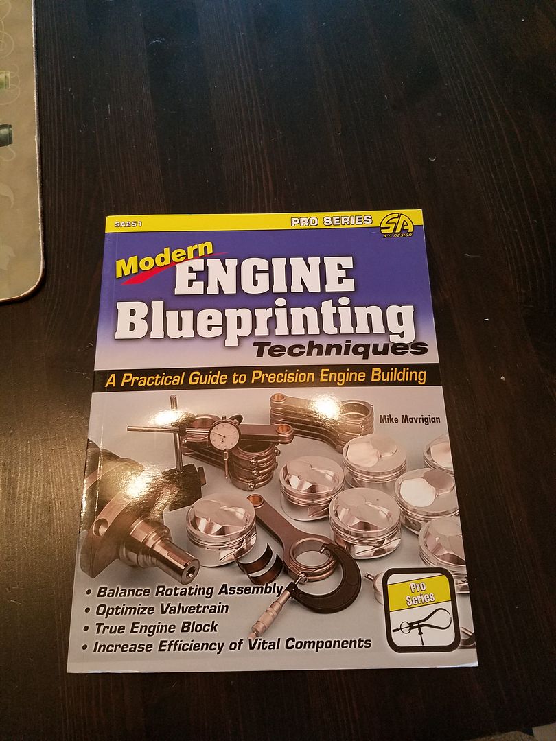


    one of the biggest fears i had about building my motor was ruining the reliability of it...currently it burns practically zero oil, to the point where i add no oil at all between 5,000 intervals and the oil level is still at the top of the stick when i change it...

    from what i've read so far, motors are all about tolerances and the reliability of said motor is the result of a RANGE of acceptable tolerances due to manufacturing realities...when blueprinting a motor the goal is to build a motor that matches the original OEM design specs with a close to ZERO tolerances as possible...this concept has allayed my fears of burning oil since a light bulb went off in my head about piston rings and the tolerances around them...too far out of spec and you'll have blow by and burn oil...this is probably why my mini r56 drinks oil like a drunken sailor...

    anyway...as ambitious as it sounds...i think blueprinting my AMB motor (after really studying the theory behind it since i've never built a motor before) is a task and undertaking i'd love to take on and document...i'd love to know if those of you who've built your motors before have done any blueprinting either partially or fully...

    for instance, on the topic of honing the cylinders, the book explains that you should use a pre-crushed head gasket, install a deck plate over the gasket, torque the head bolts to spec and subsequently hone the cylinders AFTER the deck plate, gasket and head bolts have been installed to simulate the stresses that a motor experiences under load...some blueprinters even add the bell housing certain accessories like the water pump before honing...the author explains that he built a motor which had oil blow by during races as a result of honing the cylinders PRIOR to adding the head gasket, deck plate, bell housing and timing belt pump...he explains that one cylinder was measured post race and found to be out of spec due to the weight of the bell housing and the load of the fasteners warping the cylinder thereby causing deformation of the cylinder under load...

    at the end of the day, as someone who buys cars and keeps them forever, i think that is will prove to be an invaluable skill to have...while i may not blueprint the motors for every car i own, at least i'll have the skill-set to tear into them as they approach high watermarks from a mileage standpoint...my b6 has ~160k miles and my r56 has around 56k miles...i daily the b6 since it has proven to be much more reliable than my mini...

    in any event, it will be awhile until i actually move into my condo and settle in before i actually start tearing my motor apart...which gives me time to learn more about blueprinting and the amount of labor involved...to me it sounds like an amazing long term project!!!
    Last edited by jonan; 09-04-2016 at 01:12 PM.
    Want my guns??? ΜΟΛΩΝ ΛΑΒΕ!!!

    B6 Mods:
    Fully Built Motor w/ GT2860RS and all supporting mods : My Build Thread

    RS4 Mods (sprint):
    RNS-e MKII : ECS SS : JHM Spacers : Deflapped IM : UM Tune : KW V3s : Tubi Rumore : Hotchkiss F&R SBs : 034 Diff Inserts : Phil Special Headlights w/ STI Lenses : 10 Layers : Spare 07BNS (#masterrace) : Apikol Diff & Trans Mount

  2. #2
    Veteran Member Four Rings Kevin C's Avatar
    Join Date
    Mar 28 2015
    AZ Member #
    323385
    My Garage
    1987 Dodge Raider G54B Turbo
    Location
    Portland OR, United States

    Thats a great start, one of my favorite subjects.

    To add to the thread:

    Personal experience is using local performance shops, that just holding the factory tolerances can be a challenge. Another part is that the factory clearances are a starting point, if you're building a performance engine you may intentionally deviate from those recommendations to better suite your application.

    A deck plate to pre distort the bores is a very good start. On my Mitsubishi 2.6 motor, I measured .0004" to .0006" of bore distortion from head bolt stress (it's also a pretty beefy casting). A deck plate helps to cancel most of that out. You can take the line of thinking a bit further. On a bi metal motor (aluminum head), the tension on the head bolts changes as the engine heats up. That's because the aluminum head expands more than the steel fasteners.

    Two things:

    1: The fastener is effectively a funny shaped spring that changes length with various loadings
    2: Changing the diameter of the fastener changes the spring rate. To minimize bore distortion you want the thinnest diameter fastener that will get you the clamping force you need.
    3: The elastic properties of steel are mostly independent of alloy and heat treat ( modulus of elasticity) . The variation is less than about 10%.
    4: Stiffer fasteners will increase bore distortion over temperature more than fasteners with a lower "spring rate".
    5: Most blue printing books don't address the need to increase the clamping load when machining to simulate what's going on in a warmed up engine. They sometimes mention getting the block warm to simulate hot coolant.
    6: Just using a deck plate probably gets you 90% of the possible gains.
    7: Many thin wall engines are factory honed using a deck plate. Most modern engines can be considered a thin wall casting. Casting have become lighter to save weight and reduce warm up time.


    Oil usage:
    It's a combination of the rings seating to the cylinder wall and to the piston itself. The bottom two rings have a large effect on oil usage. The ratio of top ring sealing to middle ring sealing is critical to control oil usage. If the top ring starts to lose its seal and the second ring takes on the most of the pressure, oil usage will go way up. GM found that by opening the gap on the second ring, more sealing gets done by the top ring. That increases HP and reduces oil usage.

    You know that old wives tale about doing a valve job can increase oil usage? Its actually true in some cases but its not for the reasons you might think ( better cylinder pressures). My theory is that on marginal motor where the rings are just about worn out, the new head gasket and freshly torqued bolts changes the cylinder bore distortion from where the rings had run in for most of their life. Worn rings have a harder time compensating for freshly torqued cylinder heads and the now slightly different shaped cylinder bores. Blow by increases past the top ring, so it does not build enough back pressure to fully seat. The second ring does seat and you have in instant oil burner.

    Fortunately, our motors don't seem to have a lot of ring wear issues. Back in the days of leaded gas, this was a much bigger issue. Also, leaded gas was responsible for much of the upper cylinder bore wear. Not so much the lead, but the additives to prevent it from building up errode metal on short trip drive cycles where the motor doesn't get fully warmed up.

    Modern piston rings are typically quite well made and not that hard to get to seat. Things that make it harder are the thinner the ring, the less gas pressure assist you get to press the ring against the cylinder wall. Two things create sealing, one is the natural spring of the ring and the other is combustion pressure behind the ring.

    The thinner the ring, the less area for combustion gasses to press behind it to force it against the cylinder wall. That does make them a bit harder to get to seat than older rings, still with modern rings and good machining it's not an issue. Its also another reason to make sure the gap of the second ring is to the wide side, you never ever want the second ring become the primary combustion seal.
    2003 02X Six speed swapped, RS4 RSB, H&R FSB, B7 brakes, 2.0T stroker, DSMIC's, B7 CTS K04 turbo.

  3. #3
    Veteran Member Four Rings Kevin C's Avatar
    Join Date
    Mar 28 2015
    AZ Member #
    323385
    My Garage
    1987 Dodge Raider G54B Turbo
    Location
    Portland OR, United States

    I had this in another thread, but it probably belongs here:

    My experience building motors. Every few years I end up building an engine. It seems that over time I do it less and less. It might be that I got better at it and they last longer, or that i bought a house and every free cent seems to go to a mortgage and maintenance. . My experience is that modern motors are factory built to pretty exacting tolerances and just matching what the factory did can be challenging.

    In my home shop I have a good selection of measuring tools. I have measured mains using dial bore gauges, as well as snap gauges and a micrometer. Then used a set of micrometers to measure the crank and get the actual clearance.

    Comparison measurements are always nice since the calibration of the gauge is not an issue. You're only looking to measure a difference, and not come up with an absolute number (bore diameter). This is why some shops like to fit pistons to the bore. Measure the pistons OD with a micrometer, measure the bore with a snap gauge and use the same micrometer to measure the snap gauge and you have the clearance. You may not have a perfect absolute diameter measuremnt, but you do have the important number, running clearance. Accurate absolute numbers take a bit more work. You need calibrated tools and a controlled environment as well as an experienced operator.

    The same thing applies to rod and main bearings.

    1 Dial bore Gages: I have a set of Mitutoyo gages. Very nice, but the contact surfaces are small and they sink into the bearing a few tenths. The softer the bearings, the worse the issue. Also, I hated the marks it leaves in the shells. It never seemed to hurt anything, but if it can be avoided, why not? The measured clearance always seemed to end up .0002 to .0004" large (.05 to .01mm) from the actual. A lot of work for the wrong number. On the last motor I was working on, that was enough say I had enough clearance when in fact the mains were too tight.

    This was on a motor that was notorious for having bearing issues when the boost gets turned up.

    2 Snap gauges: The standard method if your making measurements. It still takes a good feel to get the gauges square to the bore and get an accurate reading. You then need to measure the snap gage with a micrometer. Take the same gauge and measure the crank. Subtract the two to get your clearance. Getting a good repeatable number on the crank is easy. One thing I never liked is on un-hardened steel cranks, how easy it is to leave a mark. Hardened cranks? Easy, Cast iron also seems to be a bit more forgiving. Getting a good repeatable number on snap gauges takes a bit of practice and a good feel.

    At work we sometimes refer to gauge R&R studies as a method to determine if a measurement system is acceptable. Mostly because we make measuring devices and we need to know if they really work. When I build an engine, the same thinking comes to mind ( occupational hazard?). The two steps needed to get the ID of the bearing bore provide a couple of opportunities for error if your even off a little with the squareness of the tools.

    http://support.minitab.com/en-us/min...age-r-r-study/

    Personal experience says that a plastigauge is a great tool and more much less likely to have operator introduced measurement errors. It looks like a shortcut method, but in my experience, it's a great sanity check if you took all your measurements the hard way or fine all on its own.

    It may sound like I'm nit picking on tiny details. On the last engine I built the measurement error was enough to say my mains were in spec when they weren't. On a performance turbo engine know for bearing problems (non 1.8T), it's not a risk I wanted to take. The upside, is it's easy to open up clearances, getting them to be tighter, not as easy.

    Short story? Plastigauge.
    2003 02X Six speed swapped, RS4 RSB, H&R FSB, B7 brakes, 2.0T stroker, DSMIC's, B7 CTS K04 turbo.

Bookmarks

Posting Permissions

  • You may not post new threads
  • You may not post replies
  • You may not post attachments
  • You may not edit your posts
  •  


    © 2001-2024 Audizine, Audizine.com, and Driverzines.com
    Audizine is an independently owned and operated automotive enthusiast community and news website.
    Audi and the Audi logo(s) are copyright/trademark Audi AG. Audizine is not endorsed by or affiliated with Audi AG.