This system is not terribly complicated, consisting of:
- level sensors attached to front and rear control arms
- motors within headlights to aim the headlight beam
- control module
Faults can appear anywhere across the system.
To access the module you may need VCDS or VAG-COM; it's possible other 3rd-party scanners can also access this module.
The system fuse, located on the driver's-side fuse block, needs to be installed and good (PO of my car removed it to get rid of dipped beam fault)
Lastly, for the system to actually work (and allow proper headlight alignment), it cannot have any stored fault codes.
Here's my story:
- Learn the car was factory-equipped with single xenons. Try to access module with VCDS to fix poor headlight alignment.
- Discover VCDS cannot connect to Headlight Range module. WTF!!
- Check fuse. It wasn't even plugged in! At least the PO left the proper fuse as a spare... so I plugged it back in.
- OOOHHHH that's why he removed the fuse. Dipped Beam error showing on cluster display screen. That would make the car harder to sell...
- Try entering module again with VCDS: success!
- Check fault codes: stored codes for left headlight motor (01534) and also for not being aimed. Darn
 [fault code 01535 is for right headlight, for reference]
That's when my diagnostic skills kicked in:
- Plug right headlight's motor into left headlight, and vice versa. Access module to check codes and see how they shift.
- Determined left headlight motor was, in fact, the culprit. (right headlight's motor worked when plugged into left headlight, so that ruled out wiring)
- Remove motor from left headlight. Inspect.
- See nothing immediately wrong. Decide to disassemble motor to determine repairability. Worst case, I buy a new one anyways.
- Learn that these are basic stepper motors, which means they have very few moving parts that can break. All the parts of my headlight motor move smoothly and appear intact.
- Decide to probe the electrical connections since my diagnosis is leading me toward that direction. Stepper motors like this one consist of 2 coils, and you should be able to measure a similar resistance across those 2 coils.
- Found that the coils on my motor are not showing the same resistance, when measured across the connector pins!
- Onto probing connections between circuit board and connector pins. Maybe there's just a bad solder joint on a connector pin...
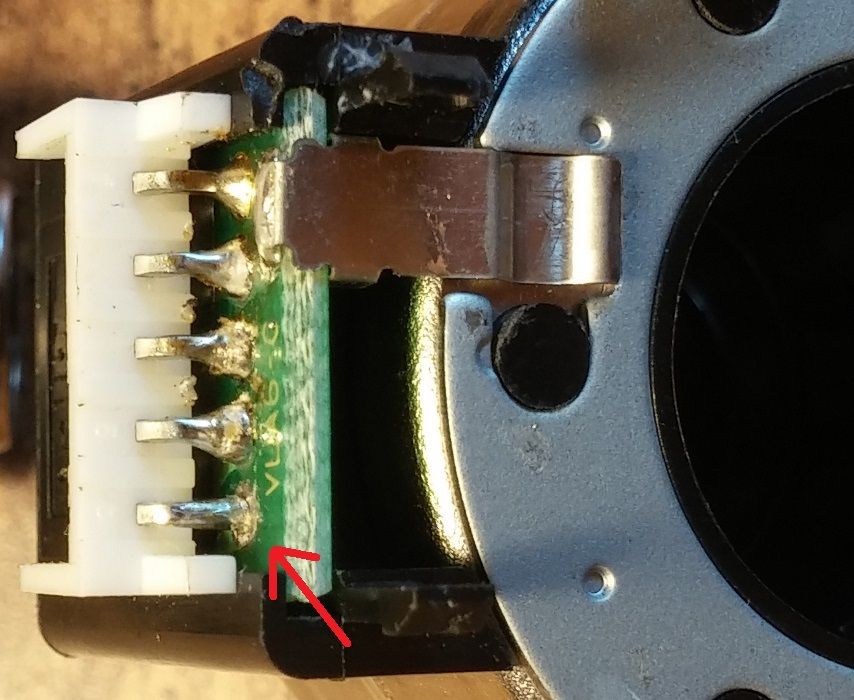
- Eureka! One of the connector pins is showing an inconsistent/higher resistance than the rest of the pins.
- Bust out the soldering iron [fine tips help here], and try resoldering that connector pin at the circuit board. I reflowed the solder on all pins for good measure.
- Put motor back together, and plug it into headlight. Check fault codes.
- Fault code for faulty headlight motor disappeared!!!!!!!!!!!!!!!
That feeling of spending only a little of your time and no money, yet saving yourself from buying a $100+ part (and MUCH MUCH more on labor if you paid a shop to do all this) is priceless.
Motor teardown and pics:
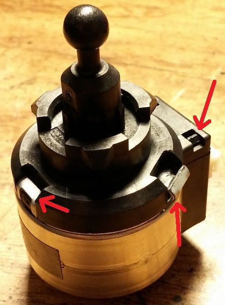
Pry back the 3 metal tabs on the case. After, you also need to push in the 2 plastic tabs. Both are indicated:
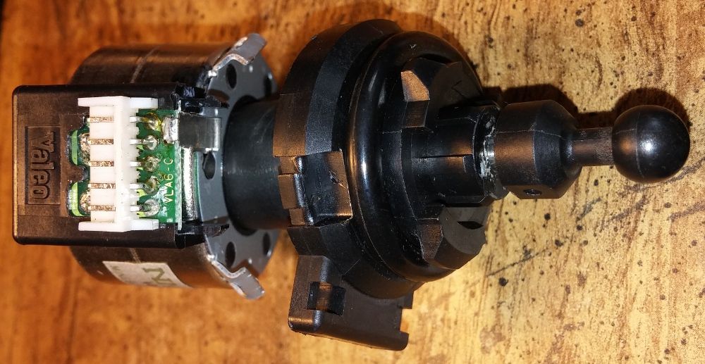
The magnet (rotor) and front end slide out from the main body (stator) with a little force:
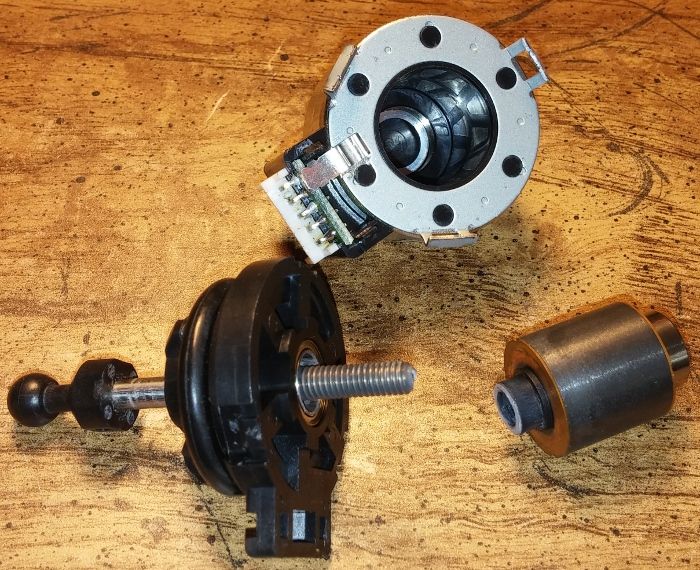
The main body (stator) at top, magnet (rotor) at right, and front end at left:
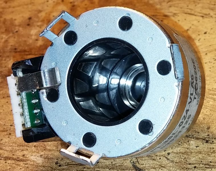
Close look at the stator, you can see the magnetic poles which a stepper motor uses:
These solder points connect directly to the stepper motor's coils, and are where I probed from to determine the poor solder joint at the connector pin:
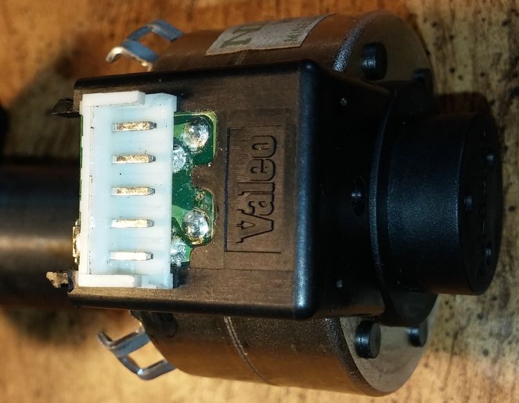
Connector pin side, where you can see the solder joints. If you look really closely at the pin indicated by an arrow, you can see a very slight crack in the solder joint:


 Reply With Quote


Bookmarks