Audizine - An Automotive Enthusiast Community

Page 1 of 10 123 ... LastLast
Results 1 to 40 of 397
  1. #1
    Veteran Member Four Rings
    Join Date
    Jun 12 2013
    AZ Member #
    117051
    My Garage
    1999 Pontiac Grand Prix GTX
    Location
    LaSalle, Ontario, Canada

    DIY: Motor work, Timing tensioner or anything with the motor and front end

    Guest-only advertisement. Register or Log In now!
    Alright Audizine members, you've all been asking for more details on a DIY, especially when it comes to the motor. I will try to assemble everything I can for you all. Bare with me on this as I expect this to be a living thread where it will be updated as I get more pictures while I’m putting my car back together. Feel free to help out as well if you’d like.
    The biggest advise I can give you is: organization! Keep bolts together with parts or put them in zip lock/sandwich bags with labels. I either do this, or a combination of using painters or masking tape and tape the bolts to the object they go with. This will save you so many headaches down the road; you’ll thank yourself 10x fold later on.

    Tools you will need:
    - Have a full set of short and long metric and SAE sockets in ¼”, 3/8” and ½” drive with ratchets and extensions to go with it
    - A full set of metric and SAE open end wrenches
    - A ‘good’ set of Torx bits. Do not put faith in the Leslie brand Torx bits, they WILL fail on you and you will want to throw something
    - A good set of screwdrivers (different lengths of flat head and Phillips)
    - I recommend ¼” Torx bits too; that way you can put them on an open end or ratcheting open end in tight places
    - A ‘good’ set of triple square bits
    - Inch pound torque wrench
    - Foot pound torque wrench
    - Razors
    - Set of picks and scrapers
    - For setting the timing, taking the harmonic balancer off, etc., you will need this kit: http://www.toolsource.com/cylinder-t...-p-150767.html
    - If you are removing the head, you will need this: http://www.toolsource.com/audi-head-...-p-114980.html
    - If you are going to replace just your timing tensioner, you will need these too: http://www.toolsource.com/locking-audi-p-99938.html

    Parts you will need:
    If you are doing prevenitive maintenance and are just replacing your timing tensioner and timing set, here is what you will need to replace:
    - Upper timing cover gasket
    - Camshaft gasket which does into the upper timing cover
    - Audi gasket/sealant (some have said you can use a Permatix one; your car, your call)
    - New crank bolt with built-in o-ring
    - (15x) timing cover bolts
    - Latest generation timing tensioner
    - Cam sprocket timing chain
    - Primary timing guide rail
    - Static timing guide rail
    - Upper track guide
    - (3x) timing guide bolts
    - O-Ring inside the intake cam valve control section of the cam bridge / cam control assembly
    - Exhaust cam bolt and spacer
    - Lower timing cover
    - Front crankshaft seal

    If you need to dig into the engine more or want to replace more wearing items (which I highly recommend), here is a list of other parts you'll need to replace:
    - Oil pump chain tensioner
    - Oil pump chain
    - Balancing shaft timing chain
    - The (3x) balance shaft guide rails
    - (5x) bolts for the balance shaft guide rails
    - Balance shaft timing tensioner


    **** I think it goes without saying, but I gotta say it: tackling this is on your own behalf. I have 15 years of engine experience under me so none of this makes me nervous. You are the best to know if this is something you can tackle or not. I take no responsibility for any mistakes and/or damage that may occur. I’m here to help you when I can though – ask any questions and I’ll reply when I can (I’m pretty active on here though).****

    Front bumper / fascia and headlights removal:
    - Remove the belly pan; main and front sections from under the car. I believe there’s 7 T30 torx bolts for this.
    - Open hood
    - Break the wheel bolts loose
    - Jack the car up and secure the car on top of jack stands. I recommend to place the jack stands right under the rear lower control arm on each side
    - Remove bolt front wheels
    - Remove the lock carrier cover; this is right in front of the hood latch, basically sitting on top of the bumper. There’s 5 expanding clip bolts – remove them. Then grab the carrier cover in the center and lift up and towards you.


    - Disconnect the connector to the outside air sensor (G17)

    - There might be other connections if you have parking sensors or other features – disconnect what is attached to the bumper. Take your time and investigate all areas
    - Remove each side’s wheel well liner; or at least the front half and you can maneuver it over the wheel hub and prop it that way so it’s out of the way. There’s a 10mm plastic nut that holds the liner to the body frame; it’s right by your brake line – remove that. There are then 4 plastic clips (I believe). I find the best way to remove them is if you have a 90* pick, get the pick under the locking tab, pull it back and then pull the clip away. Another method is to use small needle nose pliers, grab the small locking tab away and pull the clip away.
    - I ‘think’ you can leave your headlights in if you want, but I highly suggest removing them. This will not only provide you with the extra room you will want to have, but also prevent the possibility from damaging them while working within the engine compartment. In addition, you’ll be able to move wiring harnesses more out of the way to give you more real-estate to work and navigate around the engine compartment.
    These steps are for HID headlights as this is what I have; it might be different for the Halogen style headlights:
    Turn your headlight switch to ‘0’ and ensure the key is not in the ignition.
    There’s a connector right on top of the headlight, disconnect this.
    Remove a bolt that is the closest to the grille on each headlight.
    On top of the headlight is a bracket that is holding the headlight housing with a bolt going into the frame; it is the closest bolt to the fender on each side – remove that bolt.
    Right by the connector you disconnected, there’s another bolt towards the front frame – remove that one.
    You should be able to remove the headlight now by removing towards the front of the body. However, there are 2 other bolts, one on each side of the connector, loosen them just a few turns and that should allow the headlight to be removed.
    - Next is to remove the headlamp housing mounts. There are 2 bolts on the back sides of the mounts that need to be removed. You can get to them through the wheel well’s or from up top by using a ratcheting open end wrench. I think they are 10mm in size.
    - Under the car, there are (2x) T26 bolts, per side, which go into the wheel well guards’ bracket for the front fascia – remove them


    - Disconnect the connectors on each side for the fog lights

    - On each side of the wheel well, there are 2 bolts that hold a bracket which thread into the front fender. It is an odd angle to get to them, the best way I can explain it, the bolts are right behind the side of the bumper, towards the rear. I believe the 2 bolts are 10mm.
    - There are (2x) T26 bolts on top of the bumper cover / fascia, one on each side; they are right by the headlight just above the grille – remove them
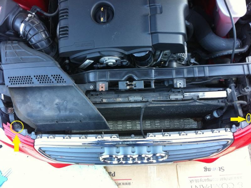
    - Remove the front fascia / bumper cover and place it to the side
    - For more details on this, feel free to use ‘Scottish_A4’s’ great DIY write-up on removing the front bumper / fascia: http://www.audizine.com/forum/showth...=1#post9479777. You can stop once the front bumper is removed, no need to touch the grille, unless you intend on swapping it out. [Credit: to Scottish_A4 as I used some of his pictures from that thread to fulfill this write-up.]. Keep in mind there are additional steps in this section as you will still need to remove those areas for this job.

    - This is what you should be looking at, at this point:

    Front Impact absorber / crash bar removal:
    - Disconnect the connection to the horn and free up the electrical harness; up and out of the way – this is on the passenger side
    - There are 2 bolts, I believe they bolt from underneath the impact bar’s brackets; 2 bolts per side.
    - Remove the impact absorber / crash bar out of its brackets and set it aside

    Intercooler and air intake assembly removal:
    - Disconnect the MAF sensor connection
    - Unscrew/open up the hose clamp on the intake air duct that’s connected to the air filter housing
    - Remove the front air duct that connects into the air filter housing; there are 2 bolts, one on each side – remove them
    - Unscrew the 4 bolts which hold the intake housing to the frame and together
    - There’s a clip on the left hand side (passenger side) of the housing, unclip it
    - Remove the top section of the air filter housing
    - Pull up and remove the lower section of the air housing and out of the engine compartment
    - Unscrew/open up the clamp on the intake air ducts on each side of the Intercooler
    - On the right hand side (driver side) there is a bolt just above the air duct line – remove the bolt
    - Remove the Intercooler by sliding it upward from the radiator and then push it to the left hand side (passenger side). Then, the right hand side (driver’s side) should go in a downward direction. Place the Intercooler off to the side.

    A/C Condensing Unit:
    - This is pretty simple; you do not need to discharge the condensing unit; you will need a few layers of cardboard, some thick foam or something similar and some rope or tie strap
    - The condensing unit is held within retaining clamps which sit on the radiators support frame. Just push the clamps towards the ‘inside’ of the engine compartment and then lift the condensing unit out. Once free, swing the condensing unit 90* clockwise, towards the driver’s side fender, place cardboard/foam between the fender and the condensing unit and then tie it up to hold it in place. Go between the frame and then fender and then around the condensing unit to hold it in place.
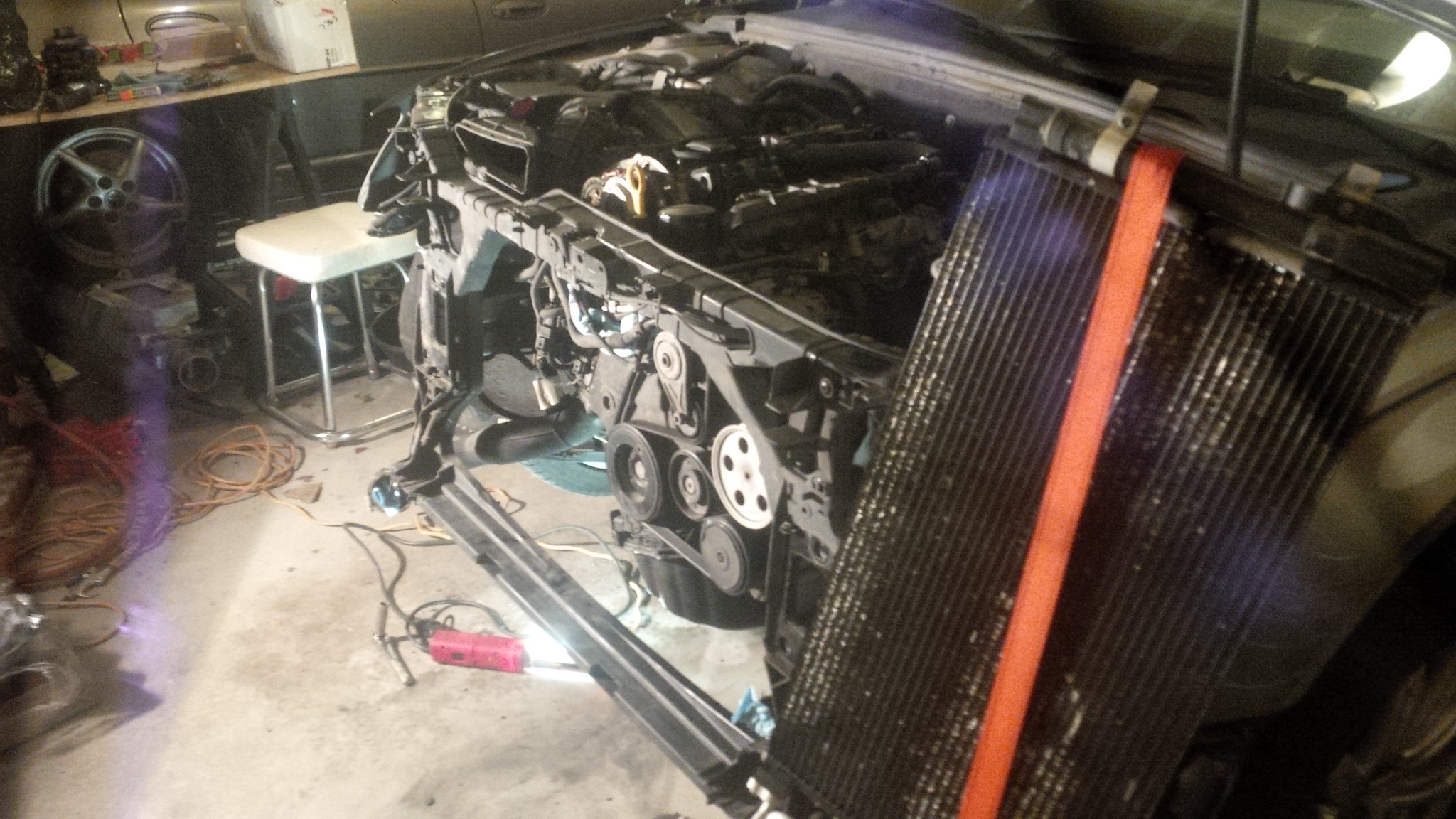
    - This should look familiar to you right now:


    Radiator:
    - Drain the coolant out of the radiator and the lower end of the cooling system. Do this by getting a catch bucket/pale and lay it on the floor towards the driver’s side. You will see the lower radiator hose and there will be a small knob which is the drain plug. Close by you will see the drain outlet port. Unscrew the drain plug as far as you can go (be cautious with it as it might be ‘stuck’; you don’t want to break it). Coolant will start to dribble/slowly drain out. This motor is a closed coolant system, you will need to open up the coolant reservoir top in order to allow air to come into the system which will increase the drainage flow. Heads up, the second you do this, the coolant drain stream will increase and you will more than likely have to re-position your catch pan/bucket.
    - There is an airbag sensor around this area (I cannot recall exactly where). Unbolt the sensor and tie it up safely and out of the way. Keep in mind to not ‘shock’ (physically) this sensor when working in the area
    - Once drained, raise the retaining clip system on the lower radiator hose that goes into the radiator then remove the hose from the radiator
    - Do the same for the upper radiator hose as you did for the lower hose
    - Plug each hoses with shop rags or shop towels to soak up the coolant that will slowly drain out and also to prevent any debris from getting into the hoses
    - Disconnect the fan connection; slide the retainer on the connection back and then press down on the release to disconnect
    - If you have an Automatic transmission, there are 2 trans lines that run into the radiator. There’s a bolt for each line, remove each bolt and then disconnect the line from the radiator (transmission fluid will drain out). Secure the lines upwards to prevent further draining and cover the lines with something (tape, cups, etc.) to avoid any debris potentially entering the open line
    - I’m fuzzy from here, but I believe there are brackets, up top, on each side for the radiator, remove them by unbolting the bolts and then pick up the radiator, removing it from the lower support and place the radiator, with the fans still connected, aside.

    Lock carrier / front frame clip:
    - There are 2 braces; one on each side, that need to be removed at the bottom of the carrier (technically they would be under the car, but everything is accessible to you now). There’s a nut that is on the other side of the embedded bolt which goes through an area of the subframe – remove the nut. Then there’s a bolt that goes through the brace and into the lock carrier / front clip – remove that bolt. Place the bolt and nut with the braces aside
    - There are 2 Torx bolts on top; one per side that need to be removed. I think they are T40’s. Remove them and the whole lock carrier will be free – have another person handy or do what I do and use your feet/legs to balance it and bring it to the ground
    At this point you should be able to hug your motor if you want to LOL; however, if you’re doing this, I think the last thing you want to do is hug it.


    Verify timing; also upper timing cover removal:
    Note: you can achieve this without having to take the whole front of the car apart. You will just have to take the belly pan sections off (I described that above). It might be kinda hard to line up the harmonic balancer’s notch to the TDC marking on the front cover from under the car, but it’s achievable.
    This is a good verification if you reassembled everything or received the car back from a shop and are having timing trouble (like a P0016 code).
    - At this point you should verify your physical cam timing. To start, remove the upper timing cover by unscrewing the (5x) T30 bolts in the cover; Note: the bolts will not come out as they have grommets which hold them in by the upper timing cover’s gasket

    There’s a bolt on top and then one to the left and the right. You will also need to take the bolt out that is holding the pseudo dipstick/breather tube (or you have made it into a dipstick like I have).

    Two more bolts are towards the bottom of the cover (you can see them unscrewed out in this pic):

    Remove the cover and set it aside.
    - You will come face to face with the exhaust and intake cam sprockets:

    - The goal is to get the notches that are in each cam sprocket to be at a top position. Do NOT go by any paint marking that you might find - these cannot be used to ID true marking. You might find paint markings if your engine had stage 2 oil consumption carried out on it or possible because of other motor work. Specifically in regards to orientation, the exhaust cam’s sprocket (left hand side/passenger’s side) at a ~11:30 o’clock position and the intake cam’s sprocket (right hand side/driver’s side) to almost a 12:30-1 o’clock position. To add, there are 3 links on the chain which are ‘marked’ (a different color). Those marks should line up right over the notches on the sprockets. Pictured below, you can see the notches in the sprockets; for the exhaust cam it’s at ~2 o’clock position and ~1 o’clock position on the intake. 2 links behind from the exhaust’s cam’s marking is the ‘marked’ link and 2 links ahead on the intake’s cam’s sprocket is the ‘marked’ link:
    To note: this is NOT how it should look, I used this picture to show what to look for
    Now, it might take up to 20 revolutions of the crank in order to get the markings to line up. The
    - Here is an impasse though, if you have got the P0016 code, you may not ever be able to get the timing to line up and you really won’t know how bad your timing is until you take the lower timing cover off so you can see where the timing mark literally is in relation to the crank sprocket is. Having said that, you make the call if you want/need to do this procedure. I’d rather you not be sitting there and turning the crank over and over to where your arm is about to fall off and it never does line up. However, if you’re carrying out this procedure because you received the car back from a shop and tripped the P0016 code, this is a good starting point. If after 30+ revolutions the timing does not match up, I hate to say it, but you’re going to have to remove the front of the car and open up the lower timing cover to 100% verify where everything is at.
    - To turn the crank / rotate the motor, use a 24mm socket on the crank bolt and rotate the harmonic balancer pulley in a clockwise direction.
    - If you see the chain ‘jump’, much like a bicycle chain when you switch gears, you know the timing tensioner is shot for sure.
    - Here is the Cylinder #1/Piston #1 TDC timing mark on the harmonic balancer pulley and the small indentation on the front cover (look closely and you’ll see the ‘–‘ indentation on the cover):

    You might have to clean off the grime and oil on your front cover to actually see the marking
    - This marking means that piston #1 is at TDC when lined up; however, it doesn’t verify what ‘stroke’ that cylinder is in. This is why you have to watch the cam sprockets and get the marks on the timing chain to line up properly for verification
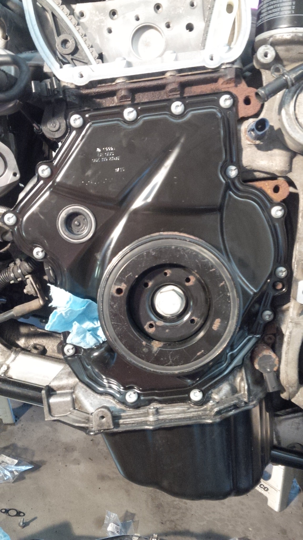
    - If you have removed the whole front end, you can also verify if the timing tensioner is toast by popping off the circle hard rubber grommet from the lower timing cover. You can see the circle grommet in this picture; it’s just to the upper left of the harmonic balancer:

    - Once you pop that off, you’ll see the timing tensioner and its piston to the right hand side. Rotate the motor over in both clockwise and counter-clockwise direction a few times. If you see the piston completely depress back into its cylinder with the primary guide rail pushing it, the tensioner is shot for sure and more than likely your timing has jumped. Here is a video of what happened to me and shows exactly what I described:


    At this point you have some options, depending on your situation, as to what you’ll want to do next. Here are my suggestions:
    - If this is a preventative maintenance measure where you just want to change out your timing set, you do not need to remove the intake manifold, turbo, cylinder head, etc. Follow the steps on how to remove the lower timing cover, removing the timing chain set and rebuild from there.
    - If you have the P0016 code and you cannot verify timing via the method I explained above, you have no choice but to remove the lower timing cover to confirm where timing is at. Based on your findings from there, here are your next options.
    • If by chance, magically, timing is ‘spot’ on, but your timing tensioner is shot (I explained earlier how you can identify how); you are one lucky S.O.B. as timing got back on. While I highly doubt this will occur, I figured I’d cover this option. All you need to do is swap out the timing set.
    • If you are 1-2 links off, you ‘should’ be ok; however, what you don’t know for sure is if interference did occur as it all depends on what stroke the cylinders were in when the slip occurred. You cannot even tell by ‘feel’ by cranking the motor over to see if a piston will hit a valve (if that’s what you’re hoping) as the motor has more torque and RPM than what you can do by hand – the damage will have already been done. Meaning ‘if’ interference did occur, the valves are already bent. I highly suggest to do a full disassembly so all components can be assessed. You do not want to just replace the timing tensioner and then realize you don’t have compression because valves are bent or further damage occurs because there were previous issues which were not addressed and left behind.
    • If you are over 2 links off, the chance of interference is much greater and you have no choice but to do a full disassembly as you’ll need to completely verify all components’ integrity.
    • If you have a broken chain – wow, “high five” but I’m sorry to hear. This usually leads to catastrophic engine damage. For sure you have no choice but to do a full disassembly, assess damage and go from there.
    Last edited by Allowencer; 05-30-2016 at 12:40 PM.
    2010 Silver Audi A4 MT Sport Package w/ B&O
    Stage 'X': FrankenTurbo F23L Ceramic Coated Manifold | Bully-Flo P&P Head | Ferrea Intake Competition Valves | Ferrera Exhaust Super Alloy Valves | IE ValveSprings & Retainers | HFC wrapped w/ DEI Titantium
    Eurocode FMIC | Maestro Tuned | K&N Typhoon Intake | EuroCode Meisterwerk | StopTech BBK | 034 Motor Mounts & All Inserts | CTS PCV Catch Can
    Build Thread

  2. #2
    Veteran Member Four Rings
    Join Date
    Jun 12 2013
    AZ Member #
    117051
    My Garage
    1999 Pontiac Grand Prix GTX
    Location
    LaSalle, Ontario, Canada

    I’ll jump into the timing replacement first before going into the removal of the intake side, exhaust side and cylinder head.

    Cam control assembly and lower timing cover and cam bridge removal:
    - Once the upper timing cover is removed (explained previously) you will see an assembly in front of the cams’ sprockets. This needs to be removed.
    - Start with the Intake Control Valve (INA valve) which is in front of the intake cam (right hand side / driver’s side). This valve is left threaded and requires T10352 or T10352/1 (depending on version) in order to unthread it and remove it. Once removed, wrap this in a lint free rag or a bag to ensure no debris or foreign material can get within it. It’s ok for this valve to have oil around it – don’t wipe it clean.
    o I’ve heard rumor that if you have a ‘full’ mechanics brake piston kit with a bunch of fittings in it, which is used on brake pistons that have to rotate back into ‘zero’ position, one of those fittings actually fits this valve. I have not verified this but heard that it’s possible. If you purchase the ‘T’ kit I mentioned previously, it will come with the correct tool.
    - There’s a M10 triple square bolt in front of the exhaust cam with a metal spacer. Remove this bolt and its spacer. This bolt is a TTY bolt, it will need to be replaced.
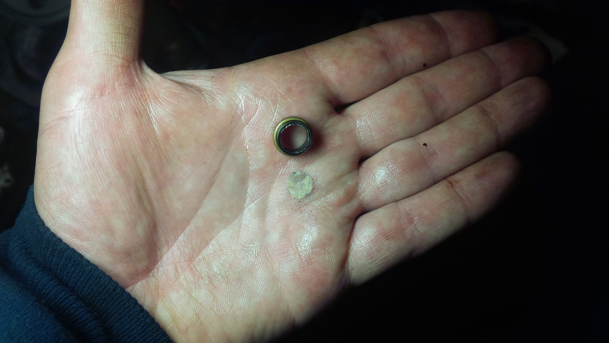
    - There are (6x) T-30 Torx bolts. Remove them and then the whole cam bridge / cam control assembly can be pulled out and away from the cams. Before placing this assembly aside, take look inside the oil galley of the assembly, which is on the side that faces the cylinder head. You will [hopefully] see a screen or you might see this:
    *Credit to lettuce for this photo
    If you see this ^, look back on the cylinder head and hopefully you see the full piece of the screen resting in the counter-sunk oil galley orifice:
    *Credit to lettuce for this photo
    o If you were able to collect the full screen, count your blessings as this didn’t go through the oil galleys and cause more issues.

    o If you cannot find the screen, this is not a good scenario and you need to find it. That means more motor disassembly. I found mine in the oil pickup screen which is in the oil pan. Hate to say it, but the worst case scenario (it has happened, I’ve talked to some shops; not trying to scare you but provide all scenarios), the screen breaks apart in small pieces, gets into the oil galleys and scores the cam journals, get’s lodged in other oil feed areas and causes oil pressure deficiency. The whole head, vacuum pump and lower assembly of the motor, at a minimum, will need to be disassembled and cleaned. I would even go as far as the whole rotating assembly too. Scary, yes, I know…
    o Hopefully you don’t have this issue at all and you see this:

    If so, great; however, I would still replace the screen with a new one
    - Remove the accessory / serpentine belt. Place a socket on the tensioner and relieve tensioner from the belt tensioner and slide the belt off of the tensioner. From there, you can unwrap the belt from all of rest of the pulleys. If you have over 50k miles on your motor, I highly recommend to replace the accessory / serpentine belt.
    - Remove the ribbed belt tensioner from the accessory bracket. This is found between the alternator and the A/C compressor. Two bolts hold it in place; remove the 2 bolts and place it aside.
    - Rotate the harmonic balancer to where the notch on the pulley lines up with the TDC marking on the lower timing cover. I explain what to look for above in the ‘Verify Timing’ section. Place T10355, which is the crank pulley counterhold, onto the harmonic balancer. There are 4 prongs on the counter hold tool which will line up to 4 prongs inside the harmonic balancer. You can see it pictured here:

    Once secured, break loose the 24mm crank bolt and then unscrew it only a turn or two. Heads up, this bolt is on pretty tight and has a significant amount of clamping force. You might need to have/build a decent size breaker bar to break this bolt loose. Remove your socket/ratchet and the counter hold tool. Get the crank spacer tool, T10368, handy. Hold the harmonic balancer pulley with one hand to ensure the pulley doesn’t move Remove the crank bolt and then slowly pull out the harmonic balancer. Insert T10368 over the crank bolt and then re-thread the crank bolt back into the crank. Tighten the crank bolt down with the spacer in place; only need to snug it down.

    The purpose of this spacer is to keep the timing sprocket sets in fwd/aft position on the crank so that when you rotate the motor, the axis won’t be off.
    - With the harmonic balancer out of the way, remove all (15x) front cover bolts.
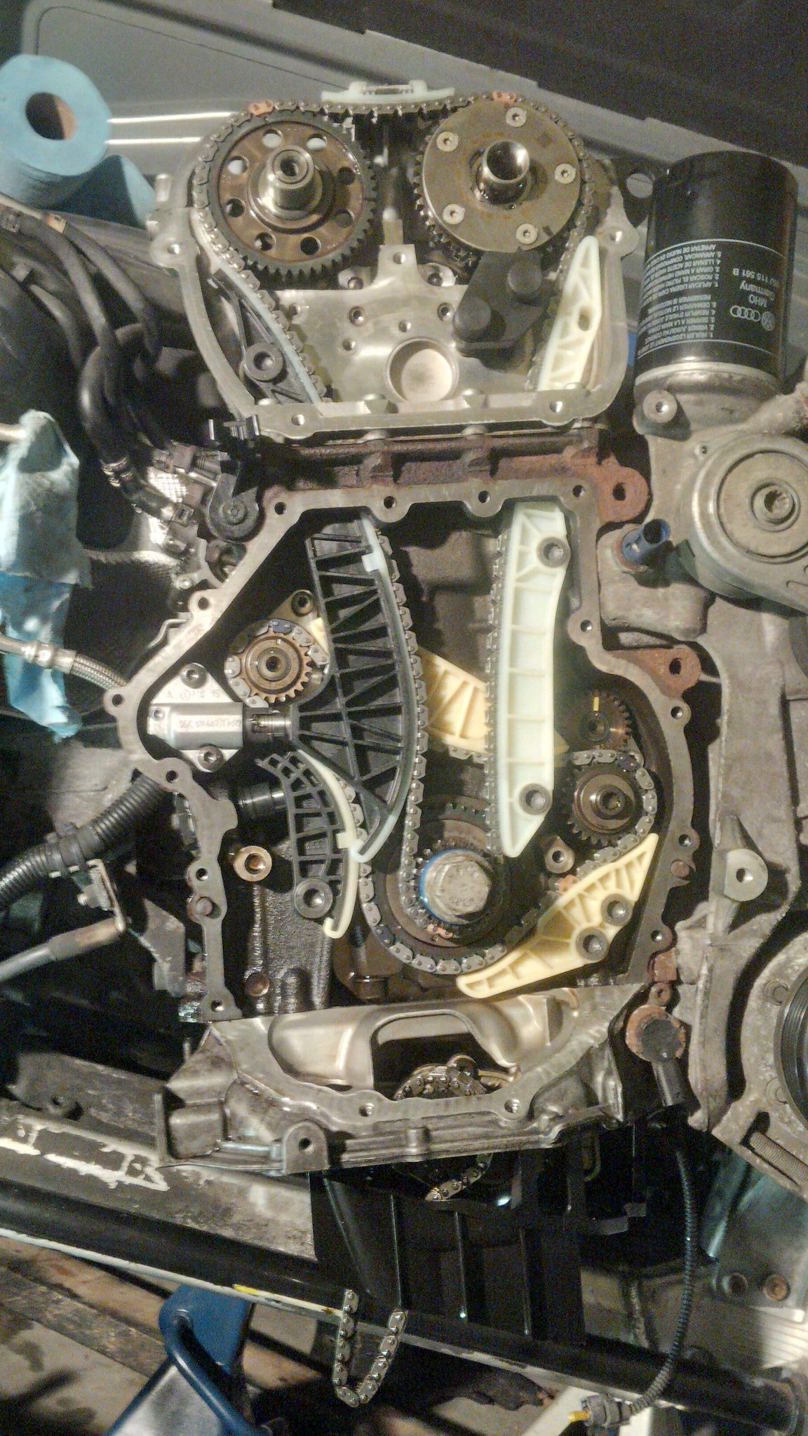
    - The front cover will be on very securely by the Audi sealant. Be advised that you more than likely will bend the lower timing cover when you remove it and you’ll need a new one. This is to be expected and occurred to me. When you go to remove it, ensure you do not mark/score the block’s mating face to the lower timing cover; you can replace the lower timing cover, not very easy to replace the block! Here is what you will be looking at with the lower timing cover removed:

    Note: I have moved the primary guide rail off of the tensioner in this pic; you will do this later on. The primary guide rail will sit higher with its ‘arm’ up against the timing tensioner’s piston.
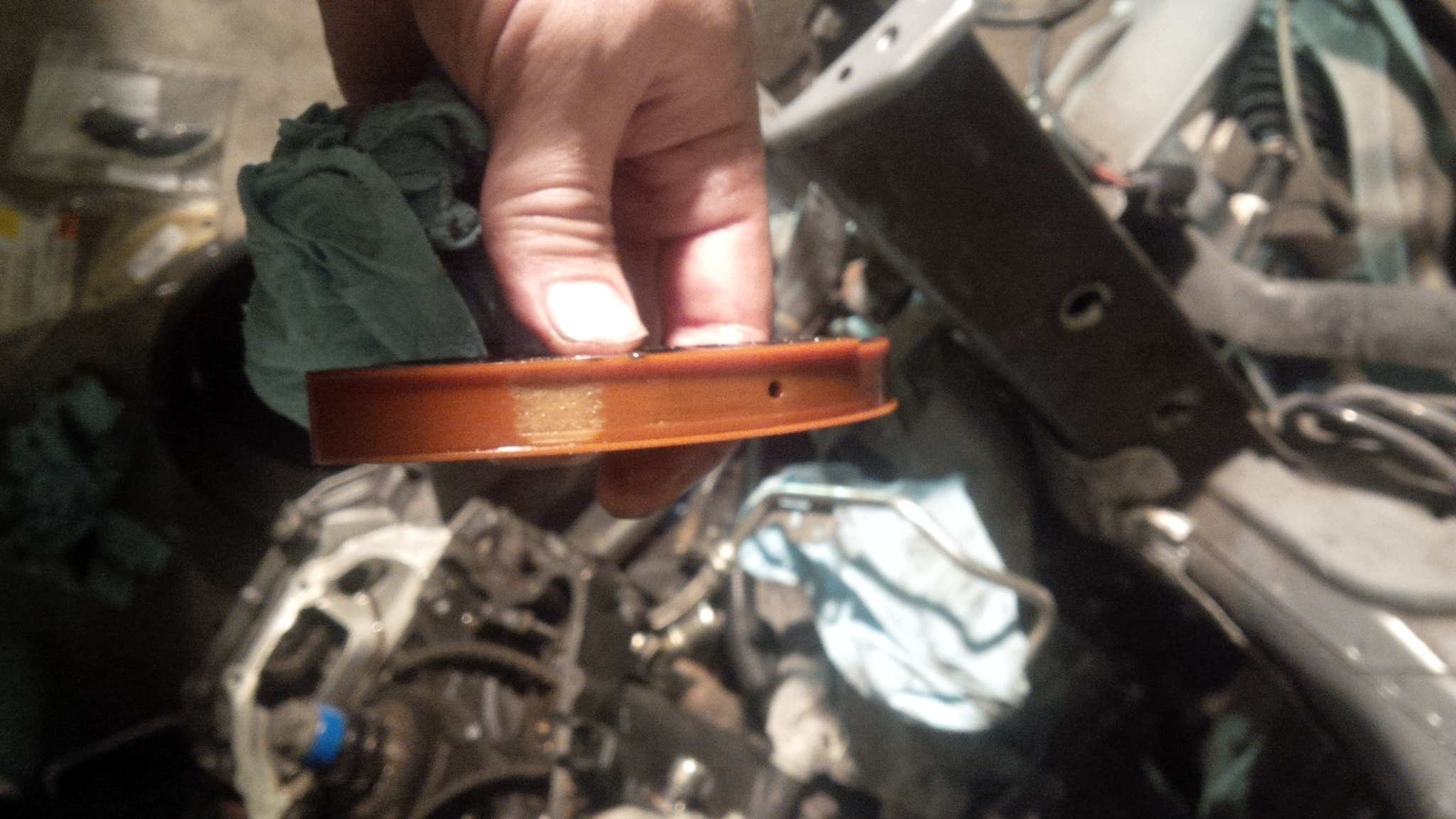
    Inspect the timing cover as well, especially if you have the P0016 code. With the timing chain having slack because of the lack of tension, the chain can catch the timing cover’s oil drain gutters. Example:


    This is what will lead to a chain failure on some engines. If there is damage to the front cover, without a doubt it needs to be replaced.

    Verify timing – Part 2
    - Now that the lower timing cover is removed, you can validate timing for sure. Rotate the motor, clockwise (as you do not want to loosen the crank bolt), until the mark on the timing chain lines up with the mark on the crank. At that point, you’ll want to record down where timing is on the cam sprockets. Here is a picture of a complete and proper timing setup; zoom in and you’ll see where the marking is on the crank sprocket and its orientation so you’ll know where TDC is for piston #1.

    - Reference back up to the 1st part of the ‘Verify timing’ section to help guide you on your options depending on how far off your timing actually is.

    Cam timing chain and guides removal
    - Remove the oil pump’s chain’s tensioner. Prior to removing the bolt, you will need to use one of the T40011 to lock the tensioner into ‘zero’ position. Do this by pushing back on the tensioner, away from the chain. At the bottom of the tensioner, you will notice there is a hole within the plastic mold. You need to push the tensioner back to where the hole will pass up the tensioner’s metal bar; place one of the T40011’s into the tensioner so it will lock it against its tension bar which will hold it into place. From there, unbolt the T30 bolt which secures the tensioner in place. Once removed, inspect the tensioner guide for any wear. I highly recommend replacing it, especially if abnormal wear is found. The oil pump’s chain can be lifted off of its timing sprocket set on the crank and then hang off to the side. No need to worry about it falling down as it doesn’t have enough room to fall off the oil pump’s sprocket in the oil pan.
    - If you are just replacing your timing set and your timing has not jumped, you will need to relieve tension on the cam timing circuit. Press on the main timing guide rail, which is the one on the left hand side, into/towards the timing tensioner. This will push the tensioner’s piston back into its bore. Towards the lower right of the tensioner you will see a small hole. Insert tool another T40011 into this hole. This will hold the tensioner at that position and prevent the tensioner’s piston from extending out further.
    - Install T40271/2 into the cylinder head on the intake side; these are the timing sprocket locks. Finger-thread the bolts into the head. You will need, IIRC a 14mm, for the intake, and a 16mm, for the exhaust cam, open end wrenches. Start with the intake camshaft and push the sprocket lock towards the head to lock the sprocket into position. More than likely you will have to use the open end wrench to rotate the cam slightly (either way is ok). Behind the intake sprocket/clutch system, you’ll see a cut out from the cam itself where the open end can seat into.

    Once the intake cam sprocket is secured, unbolt the main guide rail’s bolt on the left hand side; I believe it’s a M10 triple square. Once the bolt is removed, push on top of the main guide rail downward where you are forcing the guide rail to go down towards the floor. The idea is to get the guide rail’s ‘arm’ off of the tensioner area and also to push the guide rail down and away from the upper timing area. It should be positioned like what is shown in the picture I provided above. With the main guide rail out of the way, finger-thread the other cam lock onto the exhaust side of the head. Push the sprocket lock towards the head to lock the exhaust sprocket into position. More than likely you will have to use an open end wrench to rotate the cam slightly – ONLY rotate clockwise on the exhaust cam. Behind the exhaust cam’s sprocket you’ll see a cut out from the cam itself where the open end can seat into.

    - With both sprockets secured, remove the upper guide track by unlocking the molded latch with a flat head screwdriver and pushing/pulling the guide track forward (as pictured above as well).
    - Unbolt the static timing guide rail, the one on the right hand side; (2x) M10 triple square bolts. Remove the guide rail and inspect it for damage or abnormal wear. I highly recommend replacing all timing guide rails; it’s worth the peace of mind since all of these components wear together.
    - Remove the timing chain off of all sprockets and guide rails
    WARNING / CAUTION: DO NOT rotate the motor over, from this point forward, if the cylinder head is still assembled on top of the engine block. Doing so could very well bring a piston into contact with an open valve.
    - Pull down on the primary guide rail so it clears out from the upper timing area, it should be free then and can be removed from the engine. Inspect it for damage or abnormal wear. I highly recommend replacing all timing guide rails; it’s worth the peace of mind since all of these components wear together.
    - Unbolt the tensioner; (2x) T30 Torx bolts and do whatever you’d like with this as you feel. However, keep this and all parts you need to replace as it is evidence you might need to keep depending on how the pending class action lawsuit carries out in regards to this issue against Audi and VW group. If you’re curious as to how it failed or if yours hasn’t failed yet, I’d love to see the condition the locking pawl is in. Take the snap ring off of the timing tensioner and then pop the pawl out of its groove and flip it over. Take a picture of it and post it here so we have it documented.


    Balance shaft chain and tensioner removal:
    - CAUTION! : ENSURE the crank is not rotated out of TDC
    Here is the procedure on how to R&R the balance shaft timing chain. I highly advise you to do this since you’ve already ripped apart your motor this far. It would be like running a marathon and only going 75% of the way then stopping because you didn’t want to spend the few extra bucks. If that analogy or recommendation isn’t enough to kick you in the butt, here’s some evidence as to why you might want to; here are pictures from my balance shaft timing chain and its respective guide rails:
    The chain stretches; mind you the tensioner is a ‘static’ tensioner and does not adjust with the expected wear on the chain (old one on the left; new one on the right):


    One of the chain guides:


    I hope that was enough convincing ; moving onto the procedure to remove it:
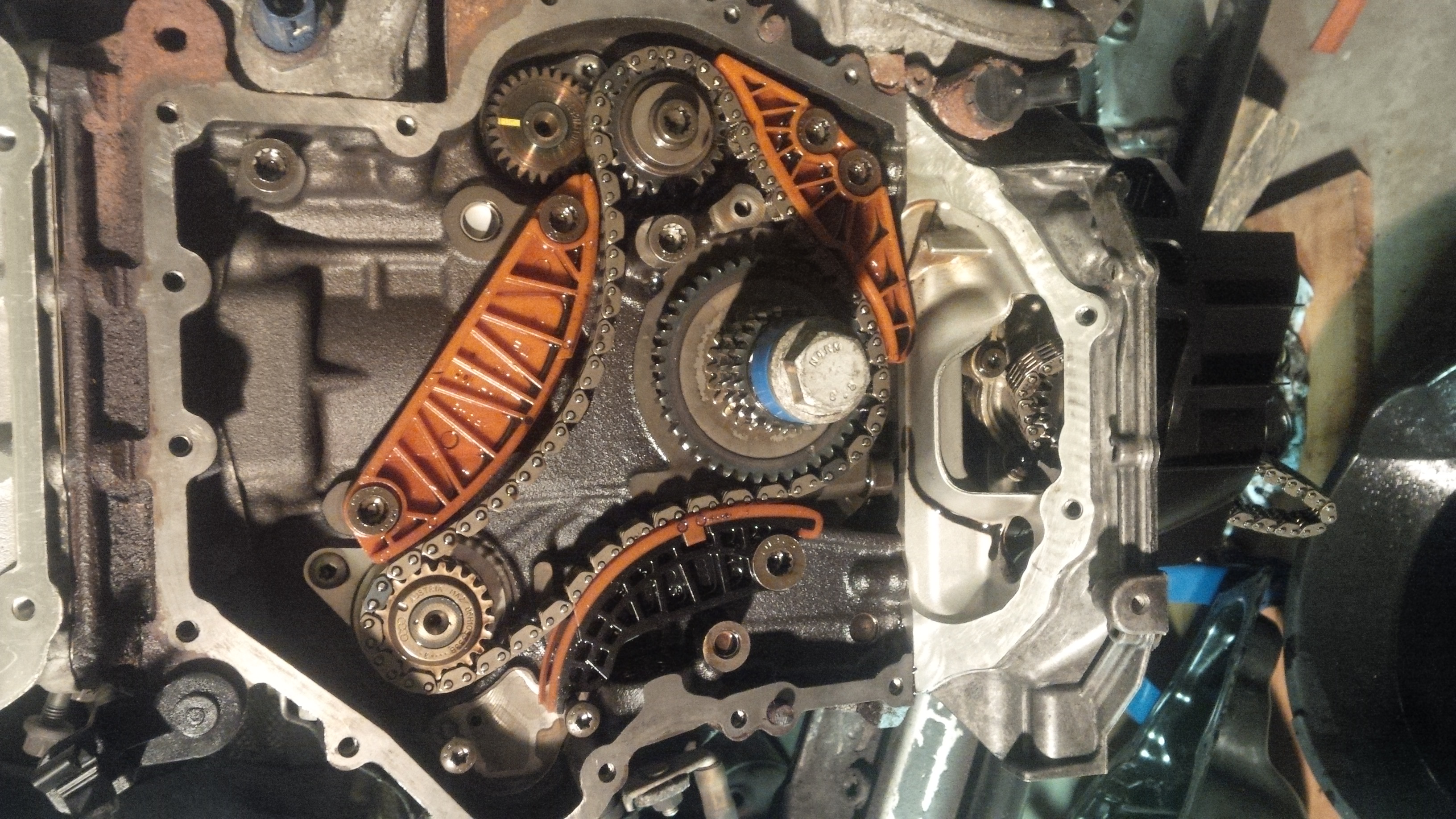
    - First remove the balance shaft chain’s timing tensioner; this is found on the left hand side of the block which has a hex ‘top’ to it. It’s a static tensioner which will unthread from the block itself.
    - Unbolt the tensioning guide rail (what the tensioner was pushing on; just to the right of the tensioner); I believe it’s a M10 triple square

    - Remove the top guide rail; (2x) M10 triple square bolts
    - Remove the lower guide rail; (2x) M10 triple square bolts
    - Remove the chain from the timing circuit

    Balance shaft chain and tensioner installation:
    - CAUTION! : ENSURE the crank is not rotated out of TDC
    - There are 2 balance shafts on this motor; one on the right hand / driver’s side and one on the left hand / passenger’s side (when looking at the motor in context to the repair). The right hand / driver’s side balance shaft is actually ‘driven’ by an intermediate sprocket set. There is a mark (a dot impression) on one of the teeth on the actual balance shaft’s sprocket (the higher and more inset of the sprockets) and then there are 2 marks (dot impressions) on the intermediate sprocket set. The mark on the balance shaft’s sprocket must line up between the 2 (basically sandwich it) marks on the intermediate sprocket set.
    - Pull out your new timing chain and familiarize yourself with the marking layouts. Rotate the chain around in order to get the timing marks the way you need them to be orientated; keeping in mind the crank cannot move and nor can the right hand side / driver’s side balance shaft. The last timing point to align is the left hand side / passenger’s side balance shaft sprocket. Lay / install the timing chain across the sprockets, ensuring the marked links line up / over to the marks on each of the 3 sprockets (left/right balance shafts and crank sprocket). Note: there is a different mark on the intermediate sprocket set which needs to correspond to the marked link on the chain; it’s not the “sandwiched” marks referenced earlier. Here is what it will need to look like (this already has the guide rails on and tensioner installed):

    - Install the lower timing guide rail with (2x) new guide rail bolts – only gently tighten them and tighten them down evenly per side
    - Install the upper timing guide rail with (2x) new guide rail bolts – only gently tighten them and tighten them down evenly per side
    - Install the timing tensioner guide rail with (1x) new guide rail bolt
    - Check the timing setting one more time (ensure all marked links line up / over to the marks on each of the 3 sprockets (left/right balance shafts and crank sprocket).
    - Install the static balance shaft timing tensioner; coat the seal (crush washer) with Audi approved sealant – CAREFUL – there is an oil feed hole right by the seal washer. You only need a slight coat of sealant on this. Once threaded down, it should be just enough to slightly squeeze out from the top [hex] of the tensioner. Torque the tensioner to: 85 Nm / 63 ft. lbs.
    - Torque all guide rail bolts to: 20 Nm / 15 ft. lbs. / 177 in. lbs.
    - If you have the cylinder head off the motor, feel free to rotate the crank over a few times to ensure the chain is aligned with the timing on each rotation. When complete, bring cylinder #1 back to TDC.
    WARNING / CAUTION: DO NOT rotate the motor over if the cylinder head is still assembled on top of the engine block. Doing so could very well bring a piston into contact with an open valve.
    Last edited by Allowencer; 05-31-2016 at 09:27 PM.

  3. #3
    Veteran Member Four Rings
    Join Date
    Jun 12 2013
    AZ Member #
    117051
    My Garage
    1999 Pontiac Grand Prix GTX
    Location
    LaSalle, Ontario, Canada

    Another reserve
    2010 Silver Audi A4 MT Sport Package w/ B&O
    Stage 'X': FrankenTurbo F23L Ceramic Coated Manifold | Bully-Flo P&P Head | Ferrea Intake Competition Valves | Ferrera Exhaust Super Alloy Valves | IE ValveSprings & Retainers | HFC wrapped w/ DEI Titantium
    Eurocode FMIC | Maestro Tuned | K&N Typhoon Intake | EuroCode Meisterwerk | StopTech BBK | 034 Motor Mounts & All Inserts | CTS PCV Catch Can
    Build Thread

  4. #4
    Veteran Member Four Rings
    Join Date
    Jun 12 2013
    AZ Member #
    117051
    My Garage
    1999 Pontiac Grand Prix GTX
    Location
    LaSalle, Ontario, Canada

    Reserve again

  5. #5
    Veteran Member Four Rings
    Join Date
    Jun 12 2013
    AZ Member #
    117051
    My Garage
    1999 Pontiac Grand Prix GTX
    Location
    LaSalle, Ontario, Canada

    Another reserve

  6. #6
    Veteran Member Four Rings
    Join Date
    Jun 12 2013
    AZ Member #
    117051
    My Garage
    1999 Pontiac Grand Prix GTX
    Location
    LaSalle, Ontario, Canada

    1 more for good measure
    2010 Silver Audi A4 MT Sport Package w/ B&O
    Stage 'X': FrankenTurbo F23L Ceramic Coated Manifold | Bully-Flo P&P Head | Ferrea Intake Competition Valves | Ferrera Exhaust Super Alloy Valves | IE ValveSprings & Retainers | HFC wrapped w/ DEI Titantium
    Eurocode FMIC | Maestro Tuned | K&N Typhoon Intake | EuroCode Meisterwerk | StopTech BBK | 034 Motor Mounts & All Inserts | CTS PCV Catch Can
    Build Thread

  7. #7
    Veteran Member Four Rings
    Join Date
    Jun 12 2013
    AZ Member #
    117051
    My Garage
    1999 Pontiac Grand Prix GTX
    Location
    LaSalle, Ontario, Canada

    maybe one more wont hurt
    2010 Silver Audi A4 MT Sport Package w/ B&O
    Stage 'X': FrankenTurbo F23L Ceramic Coated Manifold | Bully-Flo P&P Head | Ferrea Intake Competition Valves | Ferrera Exhaust Super Alloy Valves | IE ValveSprings & Retainers | HFC wrapped w/ DEI Titantium
    Eurocode FMIC | Maestro Tuned | K&N Typhoon Intake | EuroCode Meisterwerk | StopTech BBK | 034 Motor Mounts & All Inserts | CTS PCV Catch Can
    Build Thread

  8. #8
    Veteran Member Four Rings
    Join Date
    Jun 12 2013
    AZ Member #
    117051
    My Garage
    1999 Pontiac Grand Prix GTX
    Location
    LaSalle, Ontario, Canada

    And another

  9. #9
    Veteran Member Four Rings
    Join Date
    Jun 12 2013
    AZ Member #
    117051
    My Garage
    1999 Pontiac Grand Prix GTX
    Location
    LaSalle, Ontario, Canada

    might as well

  10. #10
    Veteran Member Four Rings blbroo's Avatar
    Join Date
    Oct 26 2012
    AZ Member #
    102939
    My Garage
    SQ5, Nissan D21, 435i Gone: K04'd B8 A4, M235i, UrS6, B9 SQ5, D21 Nissan 4X4
    Location
    St. Louis, MO

    Thanks for putting this together!
    Collector of German things.
    “Whoever said laughter is the best medicine had clearly never tasted scotch.”

  11. #11
    Veteran Member Four Rings Lambda13's Avatar
    Join Date
    Jul 07 2012
    AZ Member #
    96422
    My Garage
    A4, car parts, paint, random sockets, OEM parts.
    Location
    Boston, MA

    Awesome. This is fantastic.
    My 2009 A4 Prem+ Build thread

  12. #12
    Veteran Member Four Rings
    Join Date
    Sep 24 2014
    AZ Member #
    284729
    My Garage
    2015 Audi Q3 Quattro, 2017 Corvette M7 Grand Sport, 2017 Audi SQ5, 2019 Porsche Macan, 24 Jetta GLI
    Location
    Central NJ

    Excellent write-up...thanks...

    But, I don't think the rear lower control arms are a good place for the jackstands. These arms are not designed to hold the vertical weight of the car.
    Last edited by S4'ed; 05-31-2016 at 11:33 AM.

  13. #13
    Veteran Member Four Rings
    Join Date
    Jun 12 2013
    AZ Member #
    117051
    My Garage
    1999 Pontiac Grand Prix GTX
    Location
    LaSalle, Ontario, Canada

    Quote Originally Posted by S4'ed View Post
    Excellent write-up...thanks...

    But, I don't think the rear lower control arms are a good place for the jackstands. These arms are not designed to hold the vertical weight of the car.
    It's the axis of the arm that goes into the cradle / cross frame. Technically speaking, it holds the car up day to day. Maybe I should be more specific.
    2010 Silver Audi A4 MT Sport Package w/ B&O
    Stage 'X': FrankenTurbo F23L Ceramic Coated Manifold | Bully-Flo P&P Head | Ferrea Intake Competition Valves | Ferrera Exhaust Super Alloy Valves | IE ValveSprings & Retainers | HFC wrapped w/ DEI Titantium
    Eurocode FMIC | Maestro Tuned | K&N Typhoon Intake | EuroCode Meisterwerk | StopTech BBK | 034 Motor Mounts & All Inserts | CTS PCV Catch Can
    Build Thread

  14. #14
    Veteran Member Four Rings
    Join Date
    Jun 12 2013
    AZ Member #
    117051
    My Garage
    1999 Pontiac Grand Prix GTX
    Location
    LaSalle, Ontario, Canada

    Just added the R&R instructions of the balance shaft timing chain circuit
    2010 Silver Audi A4 MT Sport Package w/ B&O
    Stage 'X': FrankenTurbo F23L Ceramic Coated Manifold | Bully-Flo P&P Head | Ferrea Intake Competition Valves | Ferrera Exhaust Super Alloy Valves | IE ValveSprings & Retainers | HFC wrapped w/ DEI Titantium
    Eurocode FMIC | Maestro Tuned | K&N Typhoon Intake | EuroCode Meisterwerk | StopTech BBK | 034 Motor Mounts & All Inserts | CTS PCV Catch Can
    Build Thread

  15. #15
    Veteran Member Four Rings A4 Centaur's Avatar
    Join Date
    Jun 05 2009
    AZ Member #
    43360
    My Garage
    2020 Ducati Panigale V4S
    Location
    Scottsdale Arizona

    Such a great write-up! Thank you!
    2023 S4 Prestige Mythos Black. Brembo GT BBK, APR FMIC, 034 Stg 1
    2012 B8 A4 Avant, Phantom Black S-Line Prestige, 2014 CPMB Engine, 8 speed, JHM K04-R, Eurocode HFC, APR FMIC, 034 Alu Kreuz, Vogtland Coilovers, Stoptech 380mm BB Kit, H&R Swaybar, ECU with IE K04 Tune, Rev. "d" DV, R8 Coils, Folding Mirrors, S5 Rear Brakes, 034/Apikol mounts, OEM Facelift LED Brake lights ]

  16. #16
    Veteran Member Four Rings jjvwg's Avatar
    Join Date
    Jan 01 2012
    AZ Member #
    86019
    My Garage
    2004 A4 Avant
    Location
    CO

    This is awesome, thanks a bunch, im sure ill be using this down the road to complete mine when the time comes. all i can say is it looks like a bitch, the TB on my 1.8t is cake, this looks to be way more involved. I would have much preferred they stuck with a belt, didnt audi realize there chain systems suck after the b6/b7 chassis issues
    | 2004 A4 Avant | Gloss Dark Grey |
    | 2.7t K04 swap | 034 RSB | Apikol snub | 17z BBK |Vogtland GT1 Coilovers | Moog adj. UCA's | Peeler reps |

    | 2011 A4 Avant | Brilliant Black | 6MT swap | APR S2 | APR Downpipe | Vogtland Coilovers | RSE's | 034 Sway/tranny mount | Q5 brakes |

  17. #17
    Veteran Member Three Rings
    Join Date
    May 07 2014
    AZ Member #
    211993
    Location
    Toronto

    Most valuable threads on this site!
    2010 A4 2.0t quattro 6mt

  18. #18
    Veteran Member Three Rings
    Join Date
    Jan 13 2014
    AZ Member #
    138820
    Location
    nyc

    Quote Originally Posted by Allowencer View Post
    Just added the R&R instructions of the balance shaft timing chain circuit
    thanks for your instructions...

    did you feel vibration and a rough idle before this part failed on you?

  19. #19
    Veteran Member Three Rings K1_Builder's Avatar
    Join Date
    Mar 20 2011
    AZ Member #
    72670
    My Garage
    2009 A4 S-line MT, K-1 Attack (in progress), 2008 R1 Fiat Replica, 2008 R6 Race Bike
    Location
    Jacksonville, FL

    Appears I will be pulling my motor for new rods, pistons and rings. This is a great write up and basically covers everything I will encounter. Thanks for putting in the work.

  20. #20
    Established Member Two Rings
    Join Date
    May 02 2011
    AZ Member #
    74905
    My Garage
    '15 A6 3.0t, '14 GMC Denali Duramax, '12 F150 EcoBeast
    Location
    Casper, Wyoming

    Okay, now I need instructions on removing the cylinder head. You gonna come back and write that up?

    Also, what do you do when you come out and find that your brother in law HAS rotated the motor off of TDC?

  21. #21
    Veteran Member Four Rings Gunnark100's Avatar
    Join Date
    Oct 21 2012
    AZ Member #
    102672
    Location
    Earth...

    Quote Originally Posted by buelldozer View Post
    Okay, now I need instructions on removing the cylinder head. You gonna come back and write that up?
    Should help you a bit this file:

    Link removed!(due avoid account problem with mega), you can upload file somewhere and post again!
    Last edited by Gunnark100; 08-07-2016 at 09:01 PM.
    Retrofits: FL taillights / MMI 3G & 3G+(Street view incl.)/ Color Cluster & FL S5 Cluster/ BiXenon/ ADS Lite
    Other: ECU Tune/ VCDS Tweaks/ FL Gearknob/ Soundproofing/ Interior 6D Carbon Wrap/ Rieger Rep Front Bumper Valance/ Basic sound(8) upgrade to "ASS"(9+1) + B/O Sub(in sidepanel)/Tweeters + Activsub/ Efficiency Prog via Cluster & Gateway flash/ Sideskirts/ Window Tint/ Wsp Peeler reps/ License plate & Interior leds

  22. #22
    Established Member Two Rings
    Join Date
    May 02 2011
    AZ Member #
    74905
    My Garage
    '15 A6 3.0t, '14 GMC Denali Duramax, '12 F150 EcoBeast
    Location
    Casper, Wyoming

    Thanks but Allowncer's pictures are better. ;)

  23. #23
    Veteran Member Four Rings Gunnark100's Avatar
    Join Date
    Oct 21 2012
    AZ Member #
    102672
    Location
    Earth...

    Quote Originally Posted by buelldozer View Post
    Thanks but Allowncer's pictures are better. ;)
    Fully agree:)
    Retrofits: FL taillights / MMI 3G & 3G+(Street view incl.)/ Color Cluster & FL S5 Cluster/ BiXenon/ ADS Lite
    Other: ECU Tune/ VCDS Tweaks/ FL Gearknob/ Soundproofing/ Interior 6D Carbon Wrap/ Rieger Rep Front Bumper Valance/ Basic sound(8) upgrade to "ASS"(9+1) + B/O Sub(in sidepanel)/Tweeters + Activsub/ Efficiency Prog via Cluster & Gateway flash/ Sideskirts/ Window Tint/ Wsp Peeler reps/ License plate & Interior leds

  24. #24
    Veteran Member Three Rings DoItAllGarage's Avatar
    Join Date
    Oct 29 2013
    AZ Member #
    127509
    Location
    WA to ID

    Only few people really know how looongggg it takes to do "write-up"! Another hint that helps, the timing chain has darker links that line up the tick marks/ arrow on the gears to help line things up. I also used blue loctite on all the bolts to ensure they won't come out.

    This is what makes forums great, people like you taking time out to help others! Keep up the good work!

  25. #25
    Established Member Two Rings
    Join Date
    Oct 10 2016
    AZ Member #
    382840
    Location
    Colorado

    I'm doing a radiator job and could use a little help. I got the bumper cover removed. Do I need to remove the crash absorber and headlights so I can take the AC condenser unit out of the way? the lines are right under the crash absorber and won't move.


    Please advise.

  26. #26
    Veteran Member Four Rings A4 Centaur's Avatar
    Join Date
    Jun 05 2009
    AZ Member #
    43360
    My Garage
    2020 Ducati Panigale V4S
    Location
    Scottsdale Arizona

    I am getting ready to tackle this work in a few days time.

    I have ordered the tools for the work from the following companies:

    Crank Spacer Tool for holding crankshaft in position: http://www.centurytool.net/T10368_As.../asmt10368.htm

    Intake central control valve tool: https://www.toolsource.com/index.php...keyword=T10352

    Timing Chain Kit: https://www.ecstuning.com/b-genuine-...06h109158hkt2/

    Crank Holder Wrench and Camshaft locking tools: https://www.ecstuning.com/b-schwaben.../020946sch01a/

    New Crank dampner: http://www.fluidampr.com/
    2023 S4 Prestige Mythos Black. Brembo GT BBK, APR FMIC, 034 Stg 1
    2012 B8 A4 Avant, Phantom Black S-Line Prestige, 2014 CPMB Engine, 8 speed, JHM K04-R, Eurocode HFC, APR FMIC, 034 Alu Kreuz, Vogtland Coilovers, Stoptech 380mm BB Kit, H&R Swaybar, ECU with IE K04 Tune, Rev. "d" DV, R8 Coils, Folding Mirrors, S5 Rear Brakes, 034/Apikol mounts, OEM Facelift LED Brake lights ]

  27. #27
    Veteran Member Three Rings Discipulus's Avatar
    Join Date
    Sep 20 2016
    AZ Member #
    381429
    Location
    Portland, OR

    I just did this last weekend, and boy let me say it was a lot more time consuming than I anticipated!
    A half day on Friday plus a full day Saturday and Sunday. A lot of work for sure!

    There are a couple spots that appeared to be dripping oil after I got it all back together, so I'm letting the sealant cure fully before starting the motor and getting it warmed up. Hopefully those few drips of oil are just residual from the work I did. Crossing my fingers!

    Thanks @allowencer and everyone else in this thread for guiding the way!

    The only thing I had trouble with is finding the torque specs on the crank bolt and timing chain cover bolts.

  28. #28
    Veteran Member Four Rings
    Join Date
    Aug 17 2015
    AZ Member #
    349632
    Location
    California

    I knew I should have saved this page. Does anyone have a copy with the pictures??

    This is a great guide!

  29. #29
    Veteran Member Three Rings Discipulus's Avatar
    Join Date
    Sep 20 2016
    AZ Member #
    381429
    Location
    Portland, OR

    Quick update, no leaks, everything running smoothly after the new timing chains and tensioners/rails were installed. Somehow it seems to be running even better than before?? I'm sure it must be a placebo but I can't help but feel like it's smoother and has more power and throttle response.

    Sent from my SM-G930V using Audizine mobile app
    APR Stage 2 DP | JHM 207mm Crank | JHM HX | EPL TCU | JHM Race Pipes | JHM High-Flow Cats | Euro-Spec SQ5 Springs | Bilstein B8 Shocks | 034 Motor Mounts | ECS Drivetrain Inserts | ECS Aluminum Cross Brace | AFE Pro Dry air filter | 034 Silicone Intake Tube | 034 RSB | TRW metal endlinks | ECS Stainless Brake Lines | RSNAV S3
    2015 Q5 3.0T - Current
    2011 A4 6MT - Sold

  30. #30
    Veteran Member Four Rings A4 Centaur's Avatar
    Join Date
    Jun 05 2009
    AZ Member #
    43360
    My Garage
    2020 Ducati Panigale V4S
    Location
    Scottsdale Arizona

    ^ Yup, mine as well. But I also did the harmonic balancer as well. Thanks to the OP for a great write-up!
    2023 S4 Prestige Mythos Black. Brembo GT BBK, APR FMIC, 034 Stg 1
    2012 B8 A4 Avant, Phantom Black S-Line Prestige, 2014 CPMB Engine, 8 speed, JHM K04-R, Eurocode HFC, APR FMIC, 034 Alu Kreuz, Vogtland Coilovers, Stoptech 380mm BB Kit, H&R Swaybar, ECU with IE K04 Tune, Rev. "d" DV, R8 Coils, Folding Mirrors, S5 Rear Brakes, 034/Apikol mounts, OEM Facelift LED Brake lights ]

  31. #31
    Veteran Member Four Rings LionKing's Avatar
    Join Date
    Mar 09 2017
    AZ Member #
    395057
    My Garage
    2009 A6 Avant - 5.2L V10 Swapped, 2013 S4 Backroads Warrior
    Location
    MD

    Quote Originally Posted by Discipulus View Post
    Quick update, no leaks, everything running smoothly after the new timing chains and tensioners/rails were installed. Somehow it seems to be running even better than before?? I'm sure it must be a placebo but I can't help but feel like it's smoother and has more power and throttle response.

    Sent from my SM-G930V using Audizine mobile app
    Both of you, it should. Technically you aren't running off timing any more, even if it was just slightly due to stretch.
    Quote Originally Posted by A4 Centaur View Post
    ^ Yup, mine as well. But I also did the harmonic balancer as well. Thanks to the OP for a great write-up!

    Sent from my Nexus 6P using Audizine mobile app
    "Exhaust Gases go in the turbocharger and spin it, witchcraft happens, and you go faster"

  32. #32
    Veteran Member Three Rings Discipulus's Avatar
    Join Date
    Sep 20 2016
    AZ Member #
    381429
    Location
    Portland, OR

    Another forum member asked me for tips on specific parts/tools, so I figured I'd add it here so everyone can benefit.

    Parts and tools you'll definitely need:

    Timing chain kit (Double check your production date and make sure it's the right kit!)
    https://www.ecstuning.com/b-genuine-...06h109158hkt2/

    Upper Timing cover gasket:
    https://www.ecstuning.com/b-genuine-...et/06h103483c/

    **Optional** Lower Timing chain cover.
    This thing is VERY easy to bend upon removal. I was able to remove it without bending, but it is very difficult.
    https://www.ecstuning.com/b-genuine-...r/06h109210ag/

    Official Audi gasket maker sealant for lower timing cover. I bought it at a local Audi dealership for $50, though ECS has it for cheaper:
    https://www.ecstuning.com/b-genuine-...0ml/d174003m2/

    **Some people say you can use Permatex Ultra Black for this... but I preferred to use the special Audi stuff just in case because no way in hell was I going to remove that dang cover again.

    Crankshaft Pulley bolt
    https://www.uspmotorsports.com/Audi-...lley-Bolt.html
    This is a Torque to Yield bolt with a rubber gasket built in - needs to be replaced every time it's removed. I don't know the exact torque spec, but I found a Jetta with a similar motor specified 90Nm with additional 90 degrees rotation. Basically... just about as tight as you can get it.

    Required specialty tools:

    Oil chain tensioner locking pin:
    https://www.ecstuning.com/b-genuine-...in/t40011~oev/

    Timing service tool kit
    https://www.ecstuning.com/b-schwaben.../020946sch01a/
    I'm not kidding. You HAVE to have these tools in that kit. There is no way to get that Harmonic balancer off without this tool.
    There is also a special tool for removing the camshaft valve behind the upper valve cover included in this kit. This tool you can *maybe* substitute for one of these:
    This is what I used to remove the valve but it was very difficult and I ended up scratching the aluminum around the camshaft valve piece. No real damage was done but it would be very easy to mess it up, so next time I would definitely use the official Audi Tool for this.
    https://www.amazon.com/Performance-T...ke+piston+tool

    Additionally, this kit includes Camshaft locking tools. This is important, because without the camshaft being locked into place it will SLAM back to wherever the valve springs naturally rest once you remove the chain. Let me tell you, it is VERY HARD to rotate the camshaft by hand with those valve springs working against you! I could have saved probably 2-3 hours of time if I just got the locking tool, which again, is included in the above kit.

    Some bits and pieces that may help:
    Plastic putty knives for gently prying off the lower timing cover
    https://www.amazon.com/Red-Devil-471...c+putty+knives

    Abrasive nylon wheel for removing old gasket material:
    https://www.amazon.com/Dico-541-778-...GCDXACFW0S17DK

    Another thing that helped me IMMENSELY was putting little yellow sticky notes inside small ZipLock bags along with the screws that go to each component on my car. Example, screws for the front bumper go in a labeled bag, screws for the headlights go in another labeled bag.. etc. This was so handy, because after 3 days of working on this there is no way I could remember where each screw came from. I probably had 12 different labeled bags for each of the parts I pulled off.

    Oh, and if you've got a bit of extra $$$ to put into this, now would be a good time to upgrade to a Fluidampr. I couldn't afford it at the time but I wish I did. I'll have to tear apart the front of my car another day to install a Fluidampr sometime.

    https://www.ecstuning.com/b-fluidamp...ey/551231~flu/


    Some tricky parts along the way:
    Keep in mind when torquing down the screws/bolts inside the timing chain area: they are all screwing into Aluminum. These threads are fragile and cannot be over-torqued. Follow the torque specification for all these bolts. They may not feel "tight" like you're expecting, they just go snug and then rotate a little further as per the Torque-to-Yield bolt specs. I couldn't find a complete guide on Audizine, so I googled for a while and found a quick reference guide from a Q5 using the same 2.0T CAEB motor. Use this guide to find the torque specs and tightening pattern on the upper/lower timing covers.

    https://www.audiworld.com/forums/att...-spec-book.pdf


    And that's about all I can think of for the moment. Just take your time, go slow on that lower timing cover, and DOUBLE CHECK EVERYTHING before putting it back together. I nearly forgot to reinstall that camshaft valve http://www.audizine.com/forum/images...s/facepalm.gif

  33. #33
    Veteran Member Four Rings A4 Centaur's Avatar
    Join Date
    Jun 05 2009
    AZ Member #
    43360
    My Garage
    2020 Ducati Panigale V4S
    Location
    Scottsdale Arizona

    ^ Awesome, thanks for the addition to the thread.
    2023 S4 Prestige Mythos Black. Brembo GT BBK, APR FMIC, 034 Stg 1
    2012 B8 A4 Avant, Phantom Black S-Line Prestige, 2014 CPMB Engine, 8 speed, JHM K04-R, Eurocode HFC, APR FMIC, 034 Alu Kreuz, Vogtland Coilovers, Stoptech 380mm BB Kit, H&R Swaybar, ECU with IE K04 Tune, Rev. "d" DV, R8 Coils, Folding Mirrors, S5 Rear Brakes, 034/Apikol mounts, OEM Facelift LED Brake lights ]

  34. #34
    Veteran Member Four Rings
    Join Date
    Feb 24 2013
    AZ Member #
    110170
    Location
    CA

    Quick question, for those that removed the radiator and have the 2 auto transmission lines that needed to be removed, did you guys retop the tranny fluid at all?

  35. #35
    Established Member Two Rings
    Join Date
    May 28 2016
    AZ Member #
    373939
    Location
    Lake Arrowhead

    So, I didnt mark my cams to timing cus it had skipped 11 teeth and bent all my valves.
    Now, am I going to have issues when i set my timing? I figured there would be no point in marking my cams since they were off timing anyways.
    ive rotated my crank a few times with my cylinder head off to clean my pistons off of all that carbon, but its now back in TDC Position.
    Am I going to have any issues once i set my timing?


    Also, do I need to replace the screen on the cam bracket? Mine is broken, and from what ive gathered, I need to replace the whole thing, which is over $200... I dont want to have to dump more money into the thing
    Last edited by Azdramos; 10-27-2017 at 03:54 PM.

  36. #36
    Active Member One Ring
    Join Date
    Mar 06 2014
    AZ Member #
    151744
    Location
    Phoenix, AZ USA

    AZDramos I am in the process of replacing my chain tensioner. Do you have a write up on removing the cylinder head. My car threw a p0016 code but I don't know if there are any damage to the valves. But since I have majority of the car taken apart I figured better be safe than sorry.

  37. #37
    Veteran Member Three Rings
    Join Date
    Dec 03 2016
    AZ Member #
    387409
    Location
    nowhere

    This is much more elaborate of a procedure than the B7 timing belt. So many failing points in just this area alone: screen, tensioners, guides and even the drain gutter?

  38. #38
    Active Member One Ring TommySixGun's Avatar
    Join Date
    Dec 27 2017
    AZ Member #
    411664
    My Garage
    1964 Cadillac Fleetwood
    Location
    Northern Ohio

    Thanks for the write up Allowencer!! I just bought an A4 B8 with a failed tensioner and bent valves. After reading your write up I ran out out of my house to the garage and looked to see if my cam bracket screen was in place. It was not all there and today I dropped my cylinder head off at the machine shop so who knows where the rest of the screen is

  39. #39
    Established Member Three Rings
    Join Date
    Jun 17 2018
    AZ Member #
    420830
    Location
    Colorado

    Yes, thanks for the write-up Allowencer!

    So I'm going to be doing this repair myself and upon examining your write-up, it made me wonder if time could be saved by actually removing the Lock Carrier itself with all the stuff still mounted to it (radiator, AC evaporator, intercooler, etc.).

    So I found that a local shop will discharge (and then recharge) the AC evaporator for me, for super cheap. So I'm wondering what your - or others' here - thoughts are on doing it this way (as opposed to individually de-mounting the radiator, AC evaporator, intercooler, etc. from the Lock Carrier).

    Thoughts?

    Thanks in advance!

  40. #40
    Veteran Member Four Rings LionKing's Avatar
    Join Date
    Mar 09 2017
    AZ Member #
    395057
    My Garage
    2009 A6 Avant - 5.2L V10 Swapped, 2013 S4 Backroads Warrior
    Location
    MD

    Quote Originally Posted by blgilles View Post
    Yes, thanks for the write-up Allowencer!

    So I'm going to be doing this repair myself and upon examining your write-up, it made me wonder if time could be saved by actually removing the Lock Carrier itself with all the stuff still mounted to it (radiator, AC evaporator, intercooler, etc.).

    So I found that a local shop will discharge (and then recharge) the AC evaporator for me, for super cheap. So I'm wondering what your - or others' here - thoughts are on doing it this way (as opposed to individually de-mounting the radiator, AC evaporator, intercooler, etc. from the Lock Carrier).

    Thoughts?

    Thanks in advance!
    I can tell you, it's "less" room.. and even though I work at a shop with an a/c machine, I just took all of the bolts out of the bumper/support bracket and used a jack stands to keep everything away, lowered, and keep tension off of lines and hoses when I did mine. I didn't have to refill coolant, evac/recharge a/c, top off trans fluid at all. It's technically less room but still plenty to do the job and see all the marks well if you're familiar.

    Sent from my Pixel 2 XL using Tapatalk
    "Exhaust Gases go in the turbocharger and spin it, witchcraft happens, and you go faster"

Bookmarks

Posting Permissions

  • You may not post new threads
  • You may not post replies
  • You may not post attachments
  • You may not edit your posts
  •  


    © 2001-2024 Audizine, Audizine.com, and Driverzines.com
    Audizine is an independently owned and operated automotive enthusiast community and news website.
    Audi and the Audi logo(s) are copyright/trademark Audi AG. Audizine is not endorsed by or affiliated with Audi AG.