Originally Posted by
AussieDan

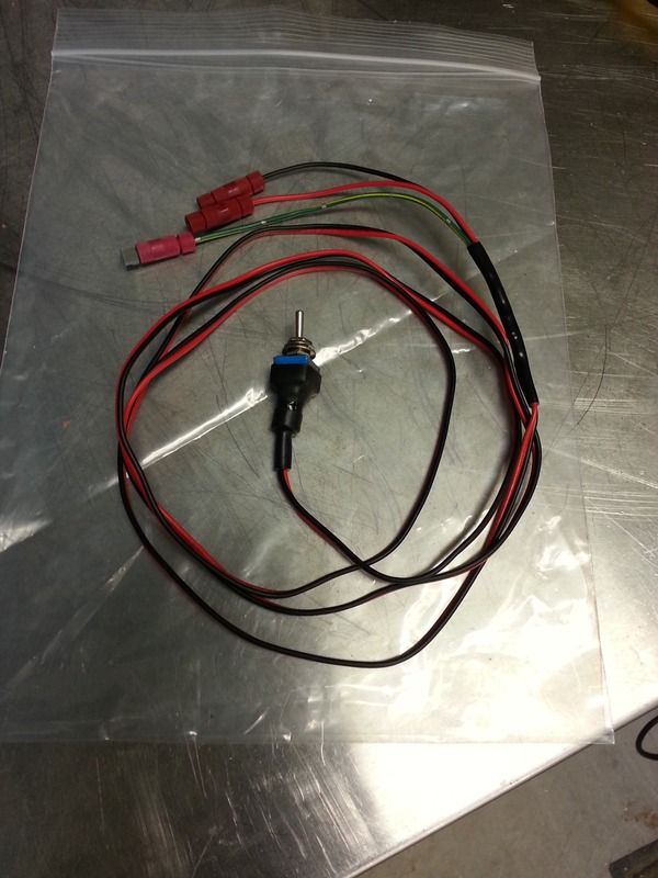
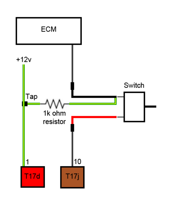
Thanks for the feedback Steve, it certainly wouldn't hurt to throw a small fuse in the circuit in case of a short, though I would note that the OEM circuit running the full length of the car back to the solenoid doesn't have any additional fuses other than the 15A fuse feeding the green/yellow 12v wire being tapped for power (the same wire present in the solenoid connector).
For the resistor I'm not sure I understand why you'd want to increase the rating so drastically, I just tested one of the 0.5w 1000ohm resistors connected across a 12.5v supply for 15 minutes and the maximum delta from ambient I could measure was 4 degrees Fahrenheit. For larger resistors the temperature rise at ~29% of rated load can get pretty extreme but at this end of the scale the 0.5w resistors don't seem to have an issue dissipating 0.144w. There is certainly no reason you couldn't step up to a higher wattage rating, but it doesn't seem to be necessary.
The 'always closed' position isn't really needed in the RS4 since that is effectively what you get with the switch off and s-mode off, but if you did want to be able to run in s-mode with the exhaust flaps closed (not sure why you'd want that) it is also possible with a DPDT switch. I know the R32 guys have done that since those cars don't have a factory mode where the flaps are closed all the time like the RS4 does (they also commonly use 1k 1/2watt resistors).
Your product definitely seems to be well thought out, and using factory-style connectors to plug in to the solenoid is a nice touch.
Hi Dan,
The recommendation for resistor rating comes from tables that describe the temperature rise for various classes of resistors. The amount of temperature rise varies. Variables include type of resistor, the surface area, how it is installed, etc. In the application that we are using where we include the resistor as a means to keep the ECU from sensing an open circuit, most designers would term that a power resistor application ... i.e., be there to burn off power when asked to do so. It is important that the resistor be sized so that the max power is not exceeded, but is well within limits. The reason is that the resistor will go up in smoke in very short order if the power exceeds capacity. At 23% of power capacity, you are getting too close for comfort. The difference in cost between a 0.5 w resistor and 5 w resistor is very small.
It is quite difficult to accurately predict what the temperature rise is likely to be. Obviously, performing an experiment such as yours is a very good way. But, when you are recommending a circuit design, unless you are very specific with regard to resistor type, manufacturer, surface area, etc. ... it would be better to over specify. What I tend to use is manufacturer ratings for temperature rise for various resistor values. One company, Ohmite, has a paper, Resistor Selection. They show a graph that depicts temperature rise vs. percent of rating. Here is a link to that paper ...
http://www.ohmite.com/techdata/res_select.pdf
I like to err on the side of caution ... so I would recommend that you specify at least a 2 watt resistor for that application ... that way you have a pretty good assurance that someone following your design will not be foiled by a blown resistor because it approached the maximum temperature rise. In the Forza controllers, I use a 5 watt resistor to make sure that the temperature rise is kept very low.
You comment about Always Closed ... in my opinion, the main use of that for an Audi and most cars is when tracking the vehicle and you want to make sure the car's ECU does not open the valves under high speed / open throttle conditions. For example, at some tracks in US and Europe, it is becoming more common that noise restrictions are becoming common place. For example, Laguna Seca in California has a 94 db noise limit and there are many examples of cars with stock exhausts (with bypass valves) where the car is keeping the valves open under wide open throttle ... the cars are failing noise requirements. To keep under the maximum noise limit, cars have to have the means to force the valves closed. You are right though, for vast majority of time, simply going back to normal mode accomplishes this. The Always Closed is only for extreme cases. One exception ... the Chevrolet Camaro. The designers at Chevy, have set up the bypass valves so they are open at engine idle up to about 1500 rpm. So some guys, who are trying to gently sneak out of the garage in the morning (or sneak in at night) are finding that the car makes too much noise at low engine RPM. They want to close those valves. This is not a problem with Audi.
In order to force the valves Always Closed, one has to apply +12V continuously to the solenoid valve(s), while simultaneously interrupting the normal circuit and shunting through the power resistor. This is not trivial to do and just putting a DPDT switch in the circuit might work out OK, but I then get back to the relay thing. Why? When you pushing +12V to the solenoid valve(s), you have higher current than you would experience through the 1000 ohm resistor. I would expect the resistance of the solenoid valve is closer to 20 ohms which would pull about 0.63 amp. I might be overstating the current .. but then again, better to err on the side of caution.
I recommended a relay and then the control wire for the relay would only be a ground wire. Yes, the risk is low running +12 v through the control wire. But if a short circuit were to occur you might cause damage. But, the risk is zero to cause damage if you use a relay and then the control wire is merely a path to ground. Then if a short circuit should occur, the worse that would happen is that the you would enable an always open condition. But you would not have sparks and smoke. For someone who has good practice of wiring, good quality connectors and work practice ... maybe not a big deal. But there are lots of people with lesser skills who might not take the care in running wires carrying load to make sure they use caution when making connection. Again, the cost of a good relay is under $5 and it mitigates a potential risk. Best practice for any control circuit in automotive and aviation is have the control wire only be a path to ground and not carry a load voltage if it can be avoided. If you look at a typical car's schematic diagrams, in nearly all cases loads are managed by relays and control of those relays is performed by managing the ground wire of the solenoid coil. Obviously there are exceptions and then fuses are placed inline.
Best regards,
Steve


 Reply With Quote


Bookmarks