Audizine - An Automotive Enthusiast Community

Page 3 of 3 FirstFirst 123
Results 81 to 115 of 115
  1. #81
    Veteran Member Four Rings
    Join Date
    Sep 11 2009
    AZ Member #
    47633
    Location
    NE

    Guest-only advertisement. Register or Log In now!
    Quote Originally Posted by bassist169 View Post
    ,

    Interesting. I've had just the opposite experience. The OE could with the ICMs went bad constantly, only lost one ICM over 10 years though. Any idea what causes the OE coils to fail so often if the ECU is calibrated to give them the right charge?
    Also, even though I haven't had any issues I'm curious whether or not the ECU can be re flashed in order to change the charge time to prevent the 2.0 coils from overcharging?
    It sure can be flashed by any shade tree tuner that does tuning on audizine etc. Traditional tuners probably can't since they have no clue what you'd ask for. Any guy who participates on nefmoto.com and does tuning as a job/side job, can do it.

  2. #82
    Veteran Member Three Rings e30mclow's Avatar
    Join Date
    Feb 08 2015
    AZ Member #
    314258
    Location
    An Irishman living in Canada

    Quote Originally Posted by julex View Post
    just get RS6 coils, they actually seal to valve covers the same way stock 2.7t do, with gaskets. 2.7t/R8 don't, there is enough "holes" for water to easily go in and play mayhem in there. I went through some 2.0t/R8 coils, failed due to water getting into the coils after car wash or heavy rain driving (only the two front ones are doing that since they are on the leading edge of engine). The worst was the first time I noticed that after about 6months of driving with these. There was about a tablespoon worth of fine powder on the bottom of spark plug hole, anybody wants to venture a guess how much water had to boil out to produce this much salt/minerals/oxidized iron and aluminum powder?
    Quote Originally Posted by julex View Post
    they're just normal dealer stuff, either local dealer or ebay or genuine if you want to do it from dealer online... 06B905115E, make sure you get genuine VW coils, they're made by Hitachi. They have white/ivory epoxied top and hitachi branding on them.
    Quote Originally Posted by julex View Post
    I've had no problems with RS6 coils for almost 6 months now beating on them with 36psi of boost daily, I would say that due to actual contact with a head, their thermal performance is much better.
    Thanks for bringing up the RS6 option!
    Does away with the overpriced spacer component of the swap, but they appear to be around $40/ea.

    I'll look into these for next time, thanks.

  3. #83
    Veteran Member Four Rings
    Join Date
    Sep 11 2009
    AZ Member #
    47633
    Location
    NE

    They're $30 a pop from VW dealer, so comparable to 2.0t junk. These coils are used in RS6, beetle and few other audi/vw models so not a special or rare part at all.

  4. #84
    Established Member Two Rings
    Join Date
    Nov 25 2009
    AZ Member #
    51209
    Location
    Lexington, KY/Orlando, FL

    Ok, little update on my experience. So I finished up with the valve gaskets and rewriting and heat shrinking all of the coil leads with pin 2 heading out to a separate ground (pictures below). Seems that at least one of my coil packs had given out already because I am having serious misfires at idle. Prior to the rewiring it my cheap little reader would at least tell me which cyl was misfiring however, now it just give me the random misfire code message- p0300. The computer I had vag com on died on me forever ago so I went to my shop. Their vag-com told us that cyl 1 and 5 were both misfiring... 5 pretty badly. The misfire seems to be much worse at idle though and it's still driving fine after the Rpms are up a bit.
    Im curious if wiring that ground pin no 2 to a solid ground on the block would give any reason why a simple reader won't show cyl faults anymore? On the plus side, I have ZERO ground faults, so this is a proper fix to the ground fault problem. I am picking up a couple new coil packs tomorrow and I'll update again if that fixes the misfire problem.

  5. #85
    Veteran Member Three Rings uponone nogaro's Avatar
    Join Date
    Sep 13 2011
    AZ Member #
    81213
    My Garage
    01 Silver S4, 00 Noggy S4 Sport Package, B8.5 Dsg S4 Dual Pulley,240sx w/2j swap
    Location
    Bay Area CA.

    Any updates bassist 19 I plan to try this tomorrow I only get a cycl 4 ignition circuit code with missfires on 4 5 6 an 3

  6. #86
    Established Member Two Rings
    Join Date
    Nov 25 2009
    AZ Member #
    51209
    Location
    Lexington, KY/Orlando, FL

    My misfire was due to a bad piston. However, my open circuit faults were totally fixed by running an independent ground to each coil. No issues so far with that fix.

  7. #87
    Veteran Member Three Rings uponone nogaro's Avatar
    Join Date
    Sep 13 2011
    AZ Member #
    81213
    My Garage
    01 Silver S4, 00 Noggy S4 Sport Package, B8.5 Dsg S4 Dual Pulley,240sx w/2j swap
    Location
    Bay Area CA.

    That sucks about the pistons and good news on the miss fire

  8. #88
    Veteran Member Three Rings uponone nogaro's Avatar
    Join Date
    Sep 13 2011
    AZ Member #
    81213
    My Garage
    01 Silver S4, 00 Noggy S4 Sport Package, B8.5 Dsg S4 Dual Pulley,240sx w/2j swap
    Location
    Bay Area CA.

    Ok I just grounded my coils to the valve covers so far so good, I must say it revs smoother and drives alot smoother since the fix

  9. #89
    Registered Member One Ring
    Join Date
    Feb 02 2016
    AZ Member #
    368161
    Location
    Mostar, Bosnia and Herzegovina

    Sorry for bump this old thread, i just have one Quick question.

    Ok, you have 4 pins on connector. You have 4 pins on S4 harness (except cylinder 1 and 3 then have 3 wires). You took all no 2 pins from all connectors and ground it separetly. What did you do with 4th wire coming from S4 harness (cyl 2,4,5 and 6)? Thank you. Is your car running properly since then?

  10. #90
    Veteran Member Three Rings e30mclow's Avatar
    Join Date
    Feb 08 2015
    AZ Member #
    314258
    Location
    An Irishman living in Canada

    I think the original solder thread stated that the 2 ground pins on the new coil side should be joined and connected to the single ground coming from the harness on those particular cylinders.
    I believe that I just joined pin 4 on the coil side to the harness side ground, and put pin 2 on the coil to ground.

    I haven't got the car at the moment, so I can't be 100% sure.

    Mine has been running misfire/open circuit free since doing the swap.
    Current: 1998 Mitsubishi Pajero Evolution
    1990 BMW E30 with 1JZ
    Previous Bad Ideas: 2000 Black Stage III (BW-K04); 2000 Imola Stage III (BW-K04)
    Previous "Better" Ideas: Euro e30 m3, Euro e34 m5, Inca Orange 2002Tii, '89 325iS, '89 318i, '90 318iS, '91 318iS, 2 X '87 316, '89 320i, '81 316 and so on..

  11. #91
    Veteran Member Three Rings okkim's Avatar
    Join Date
    Dec 07 2004
    AZ Member #
    4397
    Location
    Finland

    I'll repeat myself...
    TTL ground should go to the original ground wire, and the power ground (pin 4) to the intake ground point ( not to the valve cover ), the same where the harness ground is. 034 wiring kit is made wrong. It works with the both grounds wired to the same point (OEM wire in the wiring harness), but it is not done correctly. It can produce electrical interference. I have tested it both ways, and the correct way works better.

  12. #92
    Registered Member One Ring
    Join Date
    Feb 02 2016
    AZ Member #
    368161
    Location
    Mostar, Bosnia and Herzegovina

    So this is practically it except pin no. 2 is going to valve cover?


  13. #93
    Veteran Member Three Rings okkim's Avatar
    Join Date
    Dec 07 2004
    AZ Member #
    4397
    Location
    Finland

    No. Let me repeat again.

    TTL ground should go to the original ground, and the power ground (pin 4) to the intake ground point ( not to the valve cover )
    Technically the ground should be in one single point, and that should be the same as the wiring harness has.

  14. #94
    Registered Member One Ring
    Join Date
    Feb 02 2016
    AZ Member #
    368161
    Location
    Mostar, Bosnia and Herzegovina

    Thank you okkim, i was a little confused. I underatand now. All no. 4 pins are going to the Intake ground, not on valve cover because basically valve cover doesnt have a real ground cause it's standing on rubber seal. And no 2 pin is going to the original ground from harness. Thanks again.

  15. #95
    Veteran Member Four Rings Monty23's Avatar
    Join Date
    Oct 27 2011
    AZ Member #
    83106
    My Garage
    TOYS
    Location
    Philly Suburbs

    Quote Originally Posted by e30mclow View Post
    Time for an update of the positive kind!

    Tonight, as promised, I decided to run pin #2 ground wires to a better ground point on the cam covers, as opposed to being routed back into the old loom.
    In the interest of furthering knowledge on this coil swap method I decided to only do cylinders 4-5-6 for, and will continue to monitor and compare bank behaviour.

    Initial results? I'm back in the game, baby! Went for a drive and was hitting max PSI with no stutters or hesitation. Black lines in 2nd

    I'm going to clear all codes in the AM, drive to work, and then report back with whether or not there is a distinguishable difference between banks. The answer will obviously be yes. I'll then hopefully close out this thread (for now) and add a link within the solder method thread.

    Once again, thanks to everyone that has helped! This forum is by far the most useful and knowledgeable that I've come across!
    What pin 2 are you talking about here? Icm pin2 or coil plug pin2? I just did the solder method and am having issues with cylinder 2/3 open circuit. All the wiring has been gone through and is correct per the solder method thread. I also tried wiring the icm pin 2s to the valve covers and battery gnd with no change.

    Please help. Thanks.
    STK -> Compound Turbo Build Thread
    If you cannot do great things, do small things in a great way.

  16. #96
    Veteran Member Three Rings e30mclow's Avatar
    Join Date
    Feb 08 2015
    AZ Member #
    314258
    Location
    An Irishman living in Canada

    Coil pin #2 NOT ICM.

    I just so happen to have it here on a stand beside me:


    That comes from the 2nd pin on the coil, via the 4pin plug connector. I just added some length and a connector.
    Current: 1998 Mitsubishi Pajero Evolution
    1990 BMW E30 with 1JZ
    Previous Bad Ideas: 2000 Black Stage III (BW-K04); 2000 Imola Stage III (BW-K04)
    Previous "Better" Ideas: Euro e30 m3, Euro e34 m5, Inca Orange 2002Tii, '89 325iS, '89 318i, '90 318iS, '91 318iS, 2 X '87 316, '89 320i, '81 316 and so on..
  17. #97
    Veteran Member Four Rings Monty23's Avatar
    Join Date
    Oct 27 2011
    AZ Member #
    83106
    My Garage
    TOYS
    Location
    Philly Suburbs

    Perfect! Thanks for the quick reply. Now i get to redo all my beautifully soldered and shrink wrapped coil plugs lol.

    So pin 4 still goes to the harness right?
    STK -> Compound Turbo Build Thread
    If you cannot do great things, do small things in a great way.

  18. #98
    Veteran Member Four Rings Monty23's Avatar
    Join Date
    Oct 27 2011
    AZ Member #
    83106
    My Garage
    TOYS
    Location
    Philly Suburbs

    And is it all the coils that get pin 2 grounded to the valve cover or just cyc 1 and 4 since they are 3 wire on the harness side?
    Last edited by Monty23; 10-15-2016 at 04:42 PM.
    STK -> Compound Turbo Build Thread
    If you cannot do great things, do small things in a great way.

  19. #99
    Veteran Member Three Rings e30mclow's Avatar
    Join Date
    Feb 08 2015
    AZ Member #
    314258
    Location
    An Irishman living in Canada

    Pin 4 to the harness, yes.

    I did ALL pin 2s to individual grounds.

    As you can see in the photo, I ended up cutting out all solder and crimp & shrinking all connections (that rats nest in the top right)

    I don't know if I'll go through it all again, or if it is even worth it in the long run, but it did feel like it made a dramatic difference in the way the car revved at the time
    Current: 1998 Mitsubishi Pajero Evolution
    1990 BMW E30 with 1JZ
    Previous Bad Ideas: 2000 Black Stage III (BW-K04); 2000 Imola Stage III (BW-K04)
    Previous "Better" Ideas: Euro e30 m3, Euro e34 m5, Inca Orange 2002Tii, '89 325iS, '89 318i, '90 318iS, '91 318iS, 2 X '87 316, '89 320i, '81 316 and so on..

  20. #100
    Veteran Member Four Rings Monty23's Avatar
    Join Date
    Oct 27 2011
    AZ Member #
    83106
    My Garage
    TOYS
    Location
    Philly Suburbs

    I am going to try okkim's suggestion (coil pin 2 to harness and all coil pin 4s tied together and grounded at the IM harness ground) first and see how it runs. I'll report my results back here.
    STK -> Compound Turbo Build Thread
    If you cannot do great things, do small things in a great way.

  21. #101
    Veteran Member Four Rings Monty23's Avatar
    Join Date
    Oct 27 2011
    AZ Member #
    83106
    My Garage
    TOYS
    Location
    Philly Suburbs

    Quote Originally Posted by Monty23 View Post
    I am going to try okkim's suggestion (coil pin 2 to harness and all coil pin 4s tied together and grounded at the IM harness ground) first and see how it runs. I'll report my results back here.
    Wiring it this way produces a no start condition. Engine cranks but didn't even try to start.
    And to be more specific, I only used one ground wire of the 2 harness grounds and left the other ground in the harness open for cylinders 2,3,5, and 6 to connect to coil pin 2 with coil pin 4 going to the intake manifold harness ground (all tied at one location on the IM). Could this cause my no start?
    Last edited by Monty23; 10-16-2016 at 08:03 PM.
    STK -> Compound Turbo Build Thread
    If you cannot do great things, do small things in a great way.

  22. #102
    Veteran Member Three Rings killerkali's Avatar
    Join Date
    Jan 01 2011
    AZ Member #
    68913
    Location
    Nor cal

    If I remember correctly, I had a ton of issues and no start after doing the delete my self. I went back, left the grounds coming from the car harness cut, and bridged the individual coils grounds together,then each 3 coils to their valve cover. No issues since

  23. #103
    Veteran Member Four Rings Monty23's Avatar
    Join Date
    Oct 27 2011
    AZ Member #
    83106
    My Garage
    TOYS
    Location
    Philly Suburbs

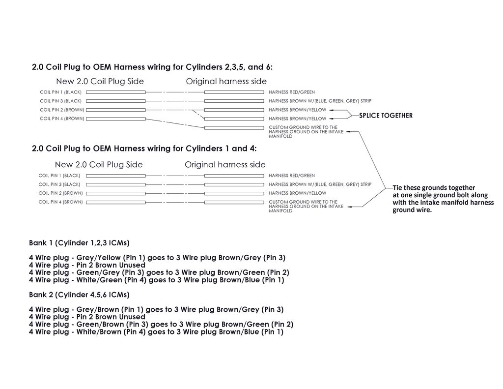
    Ok car starts and no misfires or codes at idle. All I did was tie the harness side ground together and then re attached them to coil pin 2 for coils 2,3,5, and 6. Coils 1 and 4 only have 1 ground on the harness side (3 wire). All coil pin 4s are tied together and ground at the harness ground location on the intake manifold. I'll update with a final wiring diagram once I confirm my 2.0 coil conversion is problem free.
    STK -> Compound Turbo Build Thread
    If you cannot do great things, do small things in a great way.

  24. #104
    Veteran Member Three Rings e30mclow's Avatar
    Join Date
    Feb 08 2015
    AZ Member #
    314258
    Location
    An Irishman living in Canada

    Weird that everyone has slightly different variants, but it doesn't matter as long as it is getting the cars to run right.

    If I do it again, I may just go with the 4 pin coils mentioned earlier in the thread.
    Current: 1998 Mitsubishi Pajero Evolution
    1990 BMW E30 with 1JZ
    Previous Bad Ideas: 2000 Black Stage III (BW-K04); 2000 Imola Stage III (BW-K04)
    Previous "Better" Ideas: Euro e30 m3, Euro e34 m5, Inca Orange 2002Tii, '89 325iS, '89 318i, '90 318iS, '91 318iS, 2 X '87 316, '89 320i, '81 316 and so on..

  25. #105
    Veteran Member Four Rings Monty23's Avatar
    Join Date
    Oct 27 2011
    AZ Member #
    83106
    My Garage
    TOYS
    Location
    Philly Suburbs

    Update:

    I monitored the miss-fire recognition vag-com measuring blocks 14, 15, and 16 while I idled, drove at part throttle, and at wot (30 psi boost). I have no mis-fires or stored codes and I can confidently say that my 2.0 coil wiring has been successful. Below is an image that summarizes my wiring in an easy to read visual that hopefully clears up an questions future 2.0 conversion DIYers have.

    To all, feel free to use this image in any original thread posts so that others can benefit from our troubleshooting.

    STK -> Compound Turbo Build Thread
    If you cannot do great things, do small things in a great way.

  26. #106
    Established Member Two Rings darren p.'s Avatar
    Join Date
    Nov 30 2015
    AZ Member #
    365179
    My Garage
    Mk2 GTI VR6 B5 S4 Avant E90 M3s
    Location
    NYC

    First of all, thanks to the OP and everyone that has contributed to this thread up until the end. I finally did the conversion this weekend after reading about it for the last few weeks and got stuck with open circuits and misfires after my first attempt. My issues were improper grounds to the coils. It all seems to be working fine now but I've got some questions still that the engineer in me just can't leave alone.

    Like many others, I didn't understand why cylinders 2,3,5 and 6 had 2 ground wires at the coil connector (spliced together) but cylinders 1 and 3 only had one. What I initially did was cut the connector off those 2 ground wires(brown/yellow) and used one for pin 4 and one for pin 2. This was obviously wrong but I didn't understand why. I have a spare harness thats no good that I bought for cheap for extra connectors and pigtails for when I eventually break old/brittle wires so I decided to cut it up and take a look at how those ground wires are routed. It turns out that the ground for the coil harness comes from the back of the manifold, there are 2 wires there, one for each bank. The reason there are 2 grounds at the rear 2 cylinders is simply that the ground wire for the rear cylinder loops to the middle cylinder which in turn loops to the front cylinder which is why the front cylinders only have one ground wire. So when I cut the 2 ground wires on the rear 2 cylinders, I was causing an open circuit as there was now no ground to the front 2 cylinders. Once I realized this, I fixed it by running a separate ground for pin 2 and all was well.

    What I am having a hard time understanding now is where exactly should pin 2 be grounded to? Everything in the diagram above makes perfect sense to me but I've seen this debated quite a bit and some people say valve cover and others say the back of intake manifold ground location. I ran it to the valve cover because I was concerned with interference, grounding it to the same spot as the TTL grounds on pin 4 which is where the brown/yellow ground wire in the coil harness goes as well. Does anyone have any insight on this?

    Apologies for bumping this old thread but I only got my car recently and am finally getting all of the bugs worked out (idle misfires, high boost misfires amongst other things). I will say, this site and the Nefmoto site have been so helpful and I'm looking forward to soaking up as much info as I can to get my car running optimally.

    Thanks!
    Darren

  27. #107
    Junior Member Two Rings
    Join Date
    Jan 28 2015
    AZ Member #
    311821
    Location
    Finland

    I ran new grounds for both pin 2 and 4.

    the correct way:
    Pin 2 = to original harness ground OR new ground to firewall behind coolant reservoir
    Pin 4 = intake manifold

  28. #108
    Established Member Two Rings darren p.'s Avatar
    Join Date
    Nov 30 2015
    AZ Member #
    365179
    My Garage
    Mk2 GTI VR6 B5 S4 Avant E90 M3s
    Location
    NYC

    Quote Originally Posted by bindi View Post
    I ran new grounds for both pin 2 and 4.

    the correct way:
    Pin 2 = to original harness ground OR new ground to firewall behind coolant reservoir
    Pin 4 = intake manifold
    This is what confuses me, the original harness ground goes to the intake manifold so we either tie them both together at that ground location or run a new ground to the firewall. At that point, what difference does it make if you ground to the firewall or the valve cover?

  29. #109
    Veteran Member Four Rings blitz2190's Avatar
    Join Date
    Jul 31 2014
    AZ Member #
    269656
    My Garage
    2004 A4 1.8T Quattro, 2.7T swap Stage 3 APR 6 speed
    Location
    NH

    Quote Originally Posted by bindi View Post
    I ran new grounds for both pin 2 and 4.

    the correct way:
    Pin 2 = to original harness ground OR new ground to firewall behind coolant reservoir
    Pin 4 = intake manifold
    flip those, pin 2 of all the coils should go to the two brown grounds from the 4 pin plug of the ICM's (ground connection 83), pin 4 should go to the the valve covers (engine ground connection 12) be sure to clean the stud and nut, the valve cover doesn't matter as much as its not a great ground with the rubber gasket there.

    Quote Originally Posted by darren p. View Post
    This is what confuses me, the original harness ground goes to the intake manifold so we either tie them both together at that ground location or run a new ground to the firewall. At that point, what difference does it make if you ground to the firewall or the valve cover?
    none so long as you use an appropriate gauged wire. to small and they can't draw enough current.
    Last edited by blitz2190; 04-04-2017 at 06:36 PM.
    Never argue with an idiot, they'll bring you down to their level and beat you with experience.
    2.7T Swap Wiring Guide (Psst this is a link)
    New Build In progress built 2.7 STK 2004 B6 A4- Thread and pic to come

  30. #110
    Junior Member Two Rings
    Join Date
    Jan 28 2015
    AZ Member #
    311821
    Location
    Finland

    It's been gone over a thousand times @ finnish audiforums and the final solution to grounds was as I stated, and I ran mine that way - works just fine, as it does for everyone else.

  31. #111
    Veteran Member Four Rings blitz2190's Avatar
    Join Date
    Jul 31 2014
    AZ Member #
    269656
    My Garage
    2004 A4 1.8T Quattro, 2.7T swap Stage 3 APR 6 speed
    Location
    NH

    Quote Originally Posted by bindi View Post
    It's been gone over a thousand times @ finnish audiforums and the final solution to grounds was as I stated, and I ran mine that way - works just fine, as it does for everyone else.
    ok, I was just correcting the pins and answering his question about what it matters, fyi the factory correct way would be how I said according to the wiring charts. But as long as they are getting solid good ground connections and the engine itself is grounded well(clean the engine grounding strap) they will work fine.
    Last edited by blitz2190; 04-05-2017 at 07:10 AM.
    Never argue with an idiot, they'll bring you down to their level and beat you with experience.
    2.7T Swap Wiring Guide (Psst this is a link)
    New Build In progress built 2.7 STK 2004 B6 A4- Thread and pic to come

  32. #112
    Junior Member Two Rings
    Join Date
    Jan 28 2015
    AZ Member #
    311821
    Location
    Finland

    Quote Originally Posted by blitz2190 View Post
    pin 2 of all the coils should go to the two brown grounds from the 4 pin plug of the ICM's (ground connection 83)
    So in the end this goes where the ECU ground is as well? (Pin 2 = signal ground) so to the fire wall behind the reservoir, as I said..
    Not sure if it really matters where Pin 4 is, as long as it's not the same as Pin 2. But we've been instructed to run it to the intake manifold.

  33. #113
    Veteran Member Three Rings S4gasm aka LOTR's Avatar
    Join Date
    Sep 30 2006
    AZ Member #
    12173
    My Garage
    01 S4 Santorin 6 Spd
    Location
    Missoula, MT

    Quote Originally Posted by Monty23 View Post
    Update:

    I monitored the miss-fire recognition vag-com measuring blocks 14, 15, and 16 while I idled, drove at part throttle, and at wot (30 psi boost). I have no mis-fires or stored codes and I can confidently say that my 2.0 coil wiring has been successful. Below is an image that summarizes my wiring in an easy to read visual that hopefully clears up an questions future 2.0 conversion DIYers have.

    To all, feel free to use this image in any original thread posts so that others can benefit from our troubleshooting.


    Sorry for the absolute necro-bump on this thread. But I'm curious if this is still the preferred wiring method on 2.0 coil conversion?

    I haven't driven my car much in the last few years.
    Started driving it again 2 weeks ago, running flawless for the entire time, went to wipe down my engine bay yesterday and right after that I tripped a short to ground cyl 1 and cyl 4 code. WTF right.

    I did my 2.0 conversion back in 2016 so I'm wondering if the preferred wiring method has changed since then?
    Currently I just have all my pin4 grounds tied together, grounded to the manifold.
    01 S4/ Stg 3+/K24/+stuff
    08 A6 Avant/ S-Line/ 3.2/ bone stock
    Build Thread - http://www.audizine.com/forum/showth...ld-91-craptane

  34. #114
    Veteran Member Three Rings S4gasm aka LOTR's Avatar
    Join Date
    Sep 30 2006
    AZ Member #
    12173
    My Garage
    01 S4 Santorin 6 Spd
    Location
    Missoula, MT

    Just wanted to post an update for anyone that stumbles upon this thread 5 years from now like I did lol. I know most of us old school guys don't frequent this forum much anymore so just posting for the archives.

    As e30mclow and a couple others mentioned - I ended up grounding pin2 of every coil pack to the valve cover (so each coil pack had pin2 wire grounded to a bolt holding the coil pack down), and pin4 back to the wiring harness ground.
    After trying this method I have zero faults, zero misfires, and a noticeably smoother idle. Car is absolutely ripping again.
    Cheers
    01 S4/ Stg 3+/K24/+stuff
    08 A6 Avant/ S-Line/ 3.2/ bone stock
    Build Thread - http://www.audizine.com/forum/showth...ld-91-craptane

  35. #115
    Veteran Member Four Rings
    Join Date
    May 09 2012
    AZ Member #
    93306
    Location
    Virginia

    I'm having an open to ground issue as well. For those of you that ran the pin 2 from the connector to the separate bolt on the coil pack adapter, I'm unclear if that was tied into pin 2 and pin 2 remains in the connector to the coil pack? Or is the wire that would go to the pin 2 connector pulled out and run to the bolt on the adapter without anything going to the pin 2 on the coil pack?

    From the pictures it looks like it's "y'ed" in so it has the wire going to the coil pack and a separate ground wire going to the adapter bolt?

    Supposedly the ecu is tuned to run the new 2.0 coils, but I was having ground issues. So I put in RS6 coils which fixed the ground issues, but at higher boost, I'm having misfires with the RS coils. I'm wondering if this issue is happening because the dwell time was written to run the 2.0 coils?
    Last edited by jbain2; 06-21-2024 at 07:08 PM.

Bookmarks

Posting Permissions

  • You may not post new threads
  • You may not post replies
  • You may not post attachments
  • You may not edit your posts
  •  


    © 2001-2025 Audizine, Audizine.com, and Driverzines.com
    Audizine is an independently owned and operated automotive enthusiast community and news website.
    Audi and the Audi logo(s) are copyright/trademark Audi AG. Audizine is not endorsed by or affiliated with Audi AG.