


So I'm in the middle of installing a Blaupunkt ME3 DVD with a 1417 wire converter to RCA cables thats going to the dvd player and also with Cam-Bus interface 1280 all being played on my RSN-E Nav Unit, in my 2004 A4 b6. I was wondering if you could answer a few question I have about the Cam-bus system being tapped into from a video in motion 1280 interface.
forum writeup:
http://www.audizine.com/forum/showth...-RNS-E-harness
But it left a few things out.
I know on the 1280 there are two yellow wires and two blue wires excluding the grown, power, etc that run Cam-bus. From what I understand I will be tapping into the back of pin 9 and 10 on the RSN-E navi. Those pins are Cam-Bus lines that will be passed through the 1280 interface to allows the 1280 interface to do its programing and disable the normal cam-bus operations. The top 2 wires farthest to the right on the 1280 pin wire holder is a blue wire and a yellow wire. From what I hear they go and separate the Cam-bus wires so the cam-bus feed is going through the 1280 interface and then out the other end. I will be cutting the RSNE wires adapter which feed into pin 9 and 10 directly in the middle. I will then posi-tap the RSN-E wires to the 1280 interface yellow and blue wires located on the top of the wiring pin. after that is completed I will posi-tap the yellow and blue on the next row down to the cars side of the cam-bus line making sure they are in line with how the original cam-bus wires flowed its current.

So now I have the Cam-Bus line passing through the 1280 interface to trick the Cab-Bus into thinking the car is in park while the car is in motion and out to the car engine side which the wires goes somewhere into the cubby of the center console.

My question for you relates to the Cam-bus wires being tapped into the 1280 Cam-bus interface wires. Is there a specific direction I should twist the Cam-bus wire (pin 9 and 10) coming out of the quad-lock before I Posi-Tap the quad-lock wires to the 1280 Cam-bus interface wires? I have heard from an Audi tech over the phone that the Cam-bus can be ruined and all other stuff directly related to the Cam-bus wiring will be negatively effected as a result of incorrect splicing and post-tapping. He said he knows this because it happened to a car he was working on in the past. But this was dealing with another thing and not related to the RSN-E. So if I don't cut and twist the wire in the right direction allowing for a clean connection, supposedly it will be very bad for a lot of the components that use Cam-bus in the car. He I don't know if its true since others have had success with this install. I do know what the yellow and blue wires go to.
Cam-bus low= blue
||||
Cam-bus high= yellow

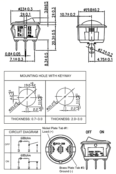
My next question for you is regarding the switch that turns on/off the 1280 cam-bus interface. From what I gather I will have a [constant power/purple 1280 switch wire/ground] all going to the rocker switch I'm going to locate in the glovebox compartment. What I have in my mind in terms of layout is this: Please refer to the diagram. Power will be taped in between the 1280 Cam-bus interface and the 1417 box from the DVD player power wires, which are both already tapped into to the RSNE quad-lock wiring harness power line (not on the diagram obviously). The power from the switch wire is connected to 12v+ power which I assume the quad-lock wiring harness can take the draw of power from all 3 sources. Which the forum writeup said it could. I could tap the battery wire near the battery power fuse on the drivers side fuse port (do you think adding a 5amp power fuse in the middle of the power switch power wire to the power being tapped into harness is a go idea for precautionary measures). I will then run the power up to the rocker switch to the number (1) tab, in the diagram. I will then take the purple wire from the 1280 cam-bus interface and run that to the middle tab which is number (2). Lastly I will run the ground from behind the glovebox to an acceptable grounding point to the number (3) tab on the bottom of the rocker switch. do you think I should just add a 5 amp fuse to the middle of the power running from the rocker switch to the tapped power line of the RSN-E, just for safe measure regardless of where I will be drawing power?
Diagram:
Hope you can share some knowledge!
Regards,
Wiley

 Reply With Quote


Bookmarks