


BOOST DUTY BACKGROUND
In order to understand what Boost Duty is you should know how the entire boost system works.
Turbocharger: A mechanical compressor that consists of two wheels. A compressor wheel and a turbine wheel. Exhaust from the exhaust ports on the engine flows into the turbine to spin the wheel which is affixed to a common driveshaft and attached to the compressor wheel. The compressor wheel is driven off of the turbine's movement, and the compressor wheel will suck in air and pressure is it into the intake tract. This compressed air goes into the intake manifold, used in the combustion process and exits the engine back into the turbo to drive the compressor wheel again.
Wastegate Actuator: A mechanical diaphragm. This diaphragm uses air pressure to move the wastegate arm. Air pressure to the diaphragm will move the arm out, no air pressure will keep the arm in its original location.
Wastegate Flapper: This is a small flap inside of the turbine housing( on internally wastegated turbos). The flapper is designed to divert exhaust flow from the turbine and allow exhaust to flow out of a port that the flapper covers. By bypassing the turbine, the compressor wheel stops or reduces building boost. The flapper is driven by the wastegate actuator arm. When air pressure entered the wastegate diaphragm, the wastegate actuator arm will move out, and will push the wastegate flapper arm down. When no pressure is applied to the wastegate diaphragm, the flapper covers the wastegate port inside of the turbine housing.
N75 Solenoid valve: This is the electronic boost controller that the ECU uses to manage boost in the system. This valve is electronically controlled, the ECU will tell it how much to open. This device has three ports that are described below. the N75 is connected to the wastegate actuator diaphragm, and is the control between how much pressurized air enters the diaphragm to control the flapper and ultimately the amount of boost produced.
BOOST DUTY TABLE
Boost duty is the N75's duty cycle, this is a value from 0% to 100%. Now here is the fun part, a percentage doesn't exactly explain well what you are doing by making edits the Boost Duty table so it's important to properly understand what you are actually doing when you manipulate the table.
N75 Description of Operation
The Boost Duty table is the ECU map that is used to control the N75. The N75 is a valve located between the turbocharger's wastegate, and the intake tract. The n75 has three nipples on it, one boost inlet, and two outlets.
Ports Described:
1. Inlet: This is where boost enters the valve, either from the intake plumbing, or more commonly the intake manifold. Simple as that.
2. Outlet to the turbo: This outlet is found perpendicular to the inlet. when Boost duty = 0%, 100% of the airflow entering the inlet (port1) is funneled through port 2 out to the wastegate actuator. What does this do? It allows the wastegate to receive pressure so that it can actuate the arm, drop the wastegate flapper inside of the turbo (if you are internally wastegated) and divert exhaust flow from the turbine to the wastegate port in the turbine housing. What this does is lower boost pressure, this is because when the wastegate actuator receives boost pressure, it opens the wastegate flapper in the turbo and you end up removing the exhaust stream from the turbine, and it escapes through the hole that the wastegate flapper covers, which reduces the amount of exhaust going into the turbine, causing less spool.
3. Outlet to the intake tract: This outlet is found inline to the boost inlet on the n75. This outlet is a "relief" to port #2, what this means is that when Boost duty is = 0%, no boost enters port #3, 100% is funneled into port #2, However as soon as boost duty is increased past 0% say to 20%, the N75 valve opens up 20%, diverting 20% of the boost now out port #3 and back into the intake tract which does nothing on that end except recirculate air. Where this matters most is in port #2. Because 20% of the flow has been diverted to port #3, you now only have 80% flow in your port #2, which means that your wastegate actuator won't be able to stay open as much as it was before. Remember that the more pressure the wastegate actuator receives, the more it can open the wastegate flapper. So an 80% flow in port #2 has now caused your wastegate flapper arm to actually close slightly, which diverts more exhaust flow into the turbine, increasing spool. You can begin to see now that there is a correlation between boost duty and boost buildup. When boost duty = 0%, most commonly under idle, all the boost pressure goes to port #2 of the N75 valve, straight to the wastegate actuator arm, allowing for the wastegate flapper to open, and not build any boost. 0% boost duty = 0% boost. On the other hand, 100% boost duty means that 100% of your boost pressure is going to Port #3, which means port #2 is getting 0% boost pressure, consequently the wastegate actuator arm receives no pressure, and the wastegate flapper remains closed, which means all exhaust flow goes to the turbine.
TL ;DR zero boost duty means no boost, low boost duty means you build low boost, high boost duty is how you build boost quickest.
K03 Boost Duty
So let's come back to the table now that we have a better understanding.

The Maestro table called Boost Duty has two inputs and one output. The inputs are RPM(speed of engine) and TPS(throttle position), these two inputs give you an output(z dimension) value if you are looking at the graph. This z output is "Boost Duty".
This table is largely driven by the turbo you are using. Let's assume its the common quick spooling K03. A k03 can range from 0 to 21 psi efficiently. Let's keep this in mind as we estimate a few values to get a feel for what we are doing.
0 % TPS and 1250 RPM's So this says, we are not trying to accelerate at all, the accelerator pedal is depressed, and we are very low in the RPM range, come to think of it, 0% throttle means you don't need boost right? After all you want boost if you want to accelerate, and at 0% throttle you can't accelerate. Make that entire column 0% all the way down.
10% TPS and 1250 RPMs. So this says we are low in the RPM range, and we want the slightest amount of boost so that we can coast, after all at 10% you aren't accelerating, it's just adding enough of the pedal so that you can continue moving at your current speed. Well in that scenario, we want just a smidge of boost, which means we want the wastegate flapper arm to close just a bit. Lets say roughly 20-25% you be the judge. We don't want too much, because if you up the boost duty to 80-100% you will build boost far too quickly, and your acceleration will feel non linear, remember that we are on a small k03 turbo which means that you can build boost very easily and quickly, so small adjustments are best.
10% TPS and 7150 RPMs. This is not a very common pedal position, but I wanted to put it down just to explain the way your graph should look like. You will have a linear increase in boost duty under 10% TPS from 1250 to 7150 RPMs, however at 10% throttle and at extremely high RPM's this k03 will be maxed out, you only need a very small increment of boost to keep the linear feel. Let's say 1/3rd extra boost duty. so if you were at 20% Boost Duty at 1250 RPMs, perhaps up it to 27% for 7150 RPMs, if you were at 25% lets go up to 33-34ish%.
Now that we have worked our way down the table let's work our way across the table.
1250 RPMS and 20% TPS, previously at 10% throttle we were requesting 23% so lets say that now we have put the pedal down 10% more, we are trying to get more power, perhaps one step above cruising but not really trying to get real acceleration, perhaps a highway pass best describes this scenario. We will want closer to 40% boost duty now so we can build a few more psi of boost, but still not have a jagged acceleration. Keep in mind that at 1250, you're K03 won't be able to make more than 10 psi, so let's keep boost duty below 50% for this 1250 RPM row. In fact the K03 doesn't really seem to respond very well below 2000 RPMs all the way from 10% to 95% TPS lets keep it all under 50%, make everything linear under there starting with the values we discussed previously.
3000 RPMs and 10% TPS. You should have filled in this value already, it should be a linear value between 20% and (20%*1.33). I used 23% for my first value (1250 and 10%) so I said 28% for 3000 RPMs and 10% TPS. Now at 3000 RPMS you are trying to move, you aren't going for maximum performance, but you definitely want to see some power, the k03 happens to be in its efficiency here, so lets make the maximum value for 3000 RPM's and 95% TPS to be something around 70%, which says that the wastegate is only open slightly, it is mostly closed. Remember than only 30% of the boost to the n75 is making it to the wastegate at this point. Considering that the k03 is so small, you should be able to see close to maximum pressure here.
Ok thats probably enough cells you get the idea. Lets consider some things here.
1. the k03 is small, it boost quickly from 2000-4000 which means you will see peak boost in this area. with such a fast spooling turbo you will want very small incremental adjustments between cells, meaning that for each value, the numbers to the left column should represent a larger gap then the numbers in the column to the right of the cell. Let me give you an example. Lets take the 10% column, this is the column with the highest change factor(delta), in column 10%, we have 0% to the left and 20% to the right. The 0% TPS column, is filled entirely of 0's! and the 10% TPS column represents numbers that should range from 20% to 35%. That is where your biggest change in columns will be. This means that from 10% to 20% the values should not increase by more than half of the change that happened from 0% TPS to 10% TPS.
Now what we can take is that the change from 0% to 10% increases very much, but the change from 10% to 20% is approximately only half of the change that happened from 0% to 10%. Consequently as you work your way across the table, changes should be smaller and smaller, so that when you reach 80% to 95% you are perhaps only changing 0.1-0.5% in the lower half of the RPM's and only 1-3% in the high RPM range.
Why?
The more throttle you add, the more boost you want, but on a k03, the spool is almost instant, meaning you can get 7 psi as soon as you step on the gas, no need for buildup like on a big turbo, so you want the wastegate arm to deliver small incremental change so that the instant spool doesn't make give you jagged acceleration. Make everything linear.
2. Your lowest values will always be in the 0% TPS column, no matter the size of the turbo, you don't need boost if you aren't accelerating. This column will always be 0% Boost Duty. Your next lowest value in a k03 Boost Duty map will be 10% TPS and 1250 RPMs, if you go down, right, or diagonally down and right, the three values will be greater than the one in 10% TPS and 1250 RPMs.
Your highest values will be where the K03 is no longer in its efficiency. So the value for 7150 RPMs and 95%TPS will be the maximum value on the map, I set it to 95%. Values to the left and above it will be less simply because the K03 is not in its efficiency range, the wastegate arm must be as closed as possible to keep exhaust flow in flowing through the turbine and not diverting to the wastegate flapper port in the turbine housing.
BIG TURBO BOOST DUTY
Lets add one of these to the equation
We will start out with a base table like this one

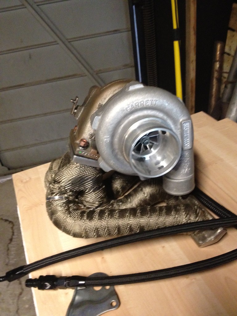
I'm running a Garrett GTX2867r on my 2.0T FSI now and what I find is that many of the maps from my k03 do not transfer well. This is especially the case for the Boost Duty Map. Now that we have an idea of how to do it on a K03, doing it on a bigger turbo should be a breeze. I like writing the table from easiest to hardest. If you can fill out the boundaries on a map you can just smooth everything with a nice linear increase. So start with what is easiest, work around the edges, then just fill in the middle values on a map with linear progressions from the lower number to the higher number across the table.
1. Start out with the usual. Write the 0% TPS column to be 0% boost duty all the way down.
2. Now let's think about where this turbo will be out of it's efficiency in the lower RPM's. Below 2000, this turbo can't build much boost, around 2500 its building a few psi, but we really get moving around 3000 and are unstoppable by 3700-4000 RPMS.
3. So under 2000 RPM's this turbo should be at maximum Boost Duty, this will ensure that most of the pressure entering the N75 leaves through Port #3 on the N75 so that the least amount of pressure enters port #2 and the wastegate can stay as closed as possible to build boost. Everything below the lowest boost threshold should be 95% Boost Duty. So I took everything under 2000 RPMS and set it to 95% Boost Duty all across the table from 10% TPS to 95% TPS. Now we have the top of this map filled.
4. Let's do the right side section of this map, which is the 95% TPS column. On a big turbo application you will not want to have 95% Boost Duty on full throttle, you want the wastegate flapper to be cracked so that you can get smoothness and quicker response. I'm not sure how far this map will take me since I'm new on this turbo so I will start out with 60% Boost Duty here all the way from 2250 RPMs to 7150 RPMs. If you run the file and feel that it isn't enough or want more boost, then up this to 65%, then 70%, then 75% and you should get a feel of how much boost each 5% is adding. I like starting low and going up from there. Remember that the borders are what matter in this map. They set the limits so you want to not push it until you know the limits. Ok now we have to do the left side this map.
5. We have already done the 0% TPS column but that doesn't mean much, so lets do the 10% column which has much more valuable information. Below 2000, we know is 95% Boost Duty. Above that from 2250 to 7150 RPM we should set a static value, maybe 5 or 10%, you can adjust this later if you feel that 10% TPS is delivering too much boost.
6. Now we have three edges of the map. 95% Boost Duty all over the top, 60% Boost Duty all along the right edge, and 5% all along the left edge. The bottom edge is easy, in fact so is all the middle of the map. Input values between the three walls that represent smooth transitions. Meaning if you're 4000 RPM column goes 0%,5% and then the final column says 60%, then the middle columns should increase evenly from 5% to 60% to fill in the values. Alternatively, if you need help, select all of the data, and right click, hit smooth data….oooh yeah thats looking nice and smooth.
7. Now the only thing we have is a block of 95% that doesn't look too smooth. Make an escalator that goes down from 0 to 30% TPS and from 1250RPM to 2000. Again make these values linear. So now that block that was 95% Boost Duty below 2000 RPMs should look like a boat, the left side of it is slanted and it looks like an upright boat. Cool right?
Upload that file to your ECU, and lets see how it plays out. Like I mentioned if you aren't getting enough boost and full throttle, up the right side to 70% or 80%, if you aren't getting enough boost at low TPS then also up the values on the left side of the map. Resmooth the values, and upload. Rinse and Repeat :).
A quick example. Lets say you want to go from 70% to 85 %
Select the right side column, and right click math functions. then type in 15 into the box and hit add. This will add the value "15" to the cells selected. However, now we have an irregular jump.

Select all of the data that you want to change, for me it was everything from the 30% TPS column to the end. Select it all, then right click, math functions. Don't type anything into the box, just hit smooth data. Boom you're done. Upload that file and see how it plays out.

If that still isn't enough then go back to the table repeat the process but try a higher boost duty this time.
One really important thing to remember is that the n75 boost duty result in different boost figures depending on how you hook up your wastegate. The rule of thumb is to bring your wastegate to where it just barely fits over the wastegate arm, then do 3 full rotations, or 6 half turns, and that is the proper value for preload on the wastegate. However, if you tighten down the wastegate much more than that, then you will need a different boost duty than what the average person would. so you will have to play with the values. It's good to know what Boost Duty results in what PSI so you don't overboost and cause damage to the engine.
When I ran the base file I was getting 21 PSI, but I wanted more. I knew 21 PSI = 70% Boost Duty, so 95% was 28 psi roughly. So I decided to not go past 95% boost duty. I am not running meth yet and I'm not sure the engine can do 30 PSI without timing pull.
So know your limits on the boost duty.
I hope this info helps, I'll be happy to fix any mistakes or inaccuracies, feel free to PM me or post here and I will edit the original information. As I keep learning about these maps I'll be sure to keep you guys in the loop so we can get a solid community of people who can teach others how to use the product.

 Reply With Quote


 Audi 5000 bitch!!!


Bookmarks