Audizine - An Automotive Enthusiast Community

Page 2 of 3 FirstFirst 123 LastLast
Results 41 to 80 of 81
  1. #41
    Veteran Member Three Rings killerkali's Avatar
    Join Date
    Jan 01 2011
    AZ Member #
    68913
    Location
    Nor cal

    Guest-only advertisement. Register or Log In now!
    dwell baloney? It still needs to be lowered, you can't argue that bud. and wow surprising that ebay shit doesnt work right?

  2. #42
    Veteran Member Four Rings Zba's Avatar
    Join Date
    Nov 05 2009
    AZ Member #
    50303
    Location
    Denver

    Quote Originally Posted by killerkali View Post
    dwell baloney? It still needs to be lowered, you can't argue that bud. and wow surprising that ebay shit doesnt work right?
    I say dwell baloney because that had nothing to do with my coils being complete garbage bro.

    I would like to see hard evidence that the dwell NEEDS to be changed. It seems like something that couldn't hurt but like everything else on the internet gets blown completely out of proportion. How many people are running around with a coil conversion that haven't changed the dwell setting and have no issues at all? The majority I'm willing to bet.

    As for the coils, they are OE coils from eBay, so yes, I had high hopes but knew in the back of my mind shit was going to go south.

    Aaaaaaaaaand it did.

  3. #43
    Active Member Two Rings
    Join Date
    Jan 29 2014
    AZ Member #
    141500
    My Garage
    b5 s4 avant stg 3 f21 e85
    Location
    Broomfield

    Quote Originally Posted by killerkali View Post
    dwell baloney? It still needs to be lowered, you can't argue that bud. and wow surprising that ebay shit doesnt work right?
    Prove it

  4. #44
    Veteran Member Three Rings killerkali's Avatar
    Join Date
    Jan 01 2011
    AZ Member #
    68913
    Location
    Nor cal

    Dont need to, im enjoying my misfire free conversion for almost 2 years now. Haven't killed any coils since I adjusted the dwell. Run stock dwell time then idgaf

  5. #45
    Veteran Member Four Rings Zba's Avatar
    Join Date
    Nov 05 2009
    AZ Member #
    50303
    Location
    Denver

    Quote Originally Posted by killerkali View Post
    Dont need to, im enjoying my misfire free conversion for almost 2 years now. Haven't killed any coils since I adjusted the dwell. Run stock dwell time then idgaf
    Why the hostility?

  6. #46
    Veteran Member Three Rings killerkali's Avatar
    Join Date
    Jan 01 2011
    AZ Member #
    68913
    Location
    Nor cal

    Didn't mean to come off as hostile lol, its a preventative recommendation i dont get why you would shoot it down. That was more towards the "prove it" useless comment.

  7. #47
    Veteran Member Four Rings Zba's Avatar
    Join Date
    Nov 05 2009
    AZ Member #
    50303
    Location
    Denver

    Quote Originally Posted by killerkali View Post
    Didn't mean to come off as hostile lol, its a preventative recommendation i dont get why you would shoot it down. That was more towards the "prove it" useless comment.
    I see. I'm not shooting it down or brushing it off. I've done plenty of reading on the subject but I've yet to see concrete proof that it's absolutely necessary, that's all.

    So you are saying you were popping couls before you adjusted dwell?

  8. #48
    Active Member Two Rings
    Join Date
    Jan 29 2014
    AZ Member #
    141500
    My Garage
    b5 s4 avant stg 3 f21 e85
    Location
    Broomfield

    Quote Originally Posted by killerkali View Post
    Dont need to, im enjoying my misfire free conversion for almost 2 years now. Haven't killed any coils since I adjusted the dwell. Run stock dwell time then idgaf
    Invalid

  9. #49
    Active Member Two Rings
    Join Date
    Jan 29 2014
    AZ Member #
    141500
    My Garage
    b5 s4 avant stg 3 f21 e85
    Location
    Broomfield

    Quote Originally Posted by killerkali View Post
    Didn't mean to come off as hostile lol, its a preventative recommendation i dont get why you would shoot it down. That was more towards the "prove it" useless comment.
    Lies

  10. #50
    Veteran Member Three Rings killerkali's Avatar
    Join Date
    Jan 01 2011
    AZ Member #
    68913
    Location
    Nor cal

    Quote Originally Posted by Zba View Post
    I see. I'm not shooting it down or brushing it off. I've done plenty of reading on the subject but I've yet to see concrete proof that it's absolutely necessary, that's all.

    So you are saying you were popping couls before you adjusted dwell?
    Yes, i went through 6 OEM coils in an insanely short time before redoing grounds and adjusting dwell. Who knows why it was though

    Quote Originally Posted by Hulksmash View Post
    Lies
    Take your useless bullshit else where ya chump

  11. #51
    Veteran Member Four Rings Monty23's Avatar
    Join Date
    Oct 27 2011
    AZ Member #
    83106
    My Garage
    TOYS
    Location
    Philly Suburbs

    My learnings from performing this 2.0 coil conversion DIY:

    Quote Originally Posted by e30mclow View Post
    Time for an update of the positive kind!

    Tonight, as promised, I decided to run pin #2 ground wires to a better ground point on the cam covers, as opposed to being routed back into the old loom.
    In the interest of furthering knowledge on this coil swap method I decided to only do cylinders 4-5-6 for, and will continue to monitor and compare bank behaviour.

    Initial results? I'm back in the game, baby! Went for a drive and was hitting max PSI with no stutters or hesitation. Black lines in 2nd

    I'm going to clear all codes in the AM, drive to work, and then report back with whether or not there is a distinguishable difference between banks. The answer will obviously be yes. I'll then hopefully close out this thread (for now) and add a link within the solder method thread.

    Once again, thanks to everyone that has helped! This forum is by far the most useful and knowledgeable that I've come across!
    Quote Originally Posted by Monty23 View Post
    What pin 2 are you talking about here? Icm pin2 or coil plug pin2? I just did the solder method and am having issues with cylinder 2/3 open circuit. All the wiring has been gone through and is correct per the solder method thread. I also tried wiring the icm pin 2s to the valve covers and battery gnd with no change.

    Please help. Thanks.
    Quote Originally Posted by Monty23 View Post
    I am going to try okkim's suggestion (coil pin 2 to harness and all coil pin 4s tied together and grounded at the IM harness ground) first and see how it runs. I'll report my results back here.
    Quote Originally Posted by Monty23 View Post
    Wiring it this way produces a no start condition. Engine cranks but didn't even try to start.
    And to be more specific, I only used one ground wire of the 2 harness grounds and left the other ground in the harness open for cylinders 2,3,5, and 6 to connect to coil pin 2 with coil pin 4 going to the intake manifold harness ground (all tied at one location on the IM). Could this cause my no start?
    Quote Originally Posted by Monty23 View Post
    Ok car starts and no misfires or codes at idle. All I did was tie the harness side ground together and then re attached them to coil pin 2 for coils 2,3,5, and 6. Coils 1 and 4 only have 1 ground on the harness side (3 wire). All coil pin 4s are tied together and ground at the harness ground location on the intake manifold. I'll update with a final wiring diagram once I confirm my 2.0 coil conversion is problem free.
    Quote Originally Posted by Monty23 View Post
    Update:

    I monitored the miss-fire recognition vag-com measuring blocks 14, 15, and 16 while I idled, drove at part throttle, and at wot (30 psi boost). I have no mis-fires or stored codes and I can confidently say that my 2.0 coil wiring has been successful. Below is an image that summarizes my wiring in an easy to read visual that hopefully clears up an questions future 2.0 conversion DIYers have.

    To all, feel free to use this image in any original thread posts so that others can benefit from our troubleshooting.

    Last edited by Monty23; 03-20-2020 at 08:54 AM. Reason: Updated photo hosting for image
    STK -> Compound Turbo Build Thread
    If you cannot do great things, do small things in a great way.

  12. #52
    Veteran Member Three Rings EMF614's Avatar
    Join Date
    Jun 15 2011
    AZ Member #
    76943
    Location
    cbus

    Hey Monty, has this wiring still held up for you? I've had all my grounds tied together for almost a year now but will occasionally get a random misfire code and hesitation while under heavy boost. I've replaced pretty much everything but I'm thinking I need to wire all the pin 4 grounds to a chassis ground.

    Thoughts anyone?

  13. #53
    Veteran Member Four Rings Zba's Avatar
    Join Date
    Nov 05 2009
    AZ Member #
    50303
    Location
    Denver

    I'd look at plugs/coils before tearing into the wiring again.

  14. #54
    Veteran Member Three Rings EMF614's Avatar
    Join Date
    Jun 15 2011
    AZ Member #
    76943
    Location
    cbus

    Plugs coils are new. The code originally shows as a cyl 6 then goes to random after another short drive. I've moved coils and plugs around and it's stayed consistant. Possibly an injector but I'm swapping those out when I pull my motor for a stk build here in a week or 2

  15. #55
    Junior Member Two Rings
    Join Date
    Jan 28 2015
    AZ Member #
    311821
    Location
    Finland

    You definitely need separate signal and power grounds, people over at the Finnish Audi forums have had weird problems with the grounds connected together - everything solved by separating grounds.

  16. #56
    Veteran Member Three Rings e30mclow's Avatar
    Join Date
    Feb 08 2015
    AZ Member #
    314258
    Location
    An Irishman living in Canada

    See my post & link at post #34.
    It solved the misfire issue for me, and isn't too difficult to rewire.

    I can't confirm the science behind it, all I can say is that it worked with my application.
    I'll use it again after I go stage 3
    Current: 1998 Mitsubishi Pajero Evolution
    1990 BMW E30 with 1JZ
    Previous Bad Ideas: 2000 Black Stage III (BW-K04); 2000 Imola Stage III (BW-K04)
    Previous "Better" Ideas: Euro e30 m3, Euro e34 m5, Inca Orange 2002Tii, '89 325iS, '89 318i, '90 318iS, '91 318iS, 2 X '87 316, '89 320i, '81 316 and so on..

  17. #57
    Veteran Member Three Rings EMF614's Avatar
    Join Date
    Jun 15 2011
    AZ Member #
    76943
    Location
    cbus

    Thanks for the info. There seems to be a lot of conflicting opinions. What I am planning on doing is snipping the pin 4 wire on the 2.0 coils, soldering in some 16 gauge wire, and ground each bank on the intake manifold. That would align with Montys diagram a few post up.

  18. #58
    Senior Member Three Rings olethalb's Avatar
    Join Date
    Feb 22 2013
    AZ Member #
    110012
    Location
    london ish

    Just followed this guide, all runs fine no misfires but lots of open circuit codes ??

    Is this a legit way to wire it?


  19. #59
    Senior Member Three Rings Bob Marley's Avatar
    Join Date
    Jan 18 2016
    AZ Member #
    367370
    Location
    Queens NY

    Seems legit... are the open codes for all cylinders or Random? Open (+) or to Ground?

    Sent from my SAMSUNG-SM-N920A using Tapatalk

  20. #60
    Senior Member Three Rings olethalb's Avatar
    Join Date
    Feb 22 2013
    AZ Member #
    110012
    Location
    london ish

    Open circuit on all cylinders

  21. #61
    Senior Member Three Rings Bob Marley's Avatar
    Join Date
    Jan 18 2016
    AZ Member #
    367370
    Location
    Queens NY

    Quote Originally Posted by olethalb View Post
    Open circuit on all cylinders
    since you say it's functioning properly...I'd focus on a non vital wire that they all have in common...

    Maybe one of the ground leads... looked like you have it running to the adapter plate bolt instead of the bolt on the valve cover...i think that screws directly to the head for a solid ground iirc.

    Sent from my SAMSUNG-SM-N920A using Tapatalk

  22. #62
    Senior Member Three Rings olethalb's Avatar
    Join Date
    Feb 22 2013
    AZ Member #
    110012
    Location
    london ish

    Thanks for the reply - these are uprated rs6 bolt down coils, the bolt goes through into the valve cover and the hole on the coil pack is metal too.

    it brings a CEL too so I hope I haven't introduced more faults with this upgrade

  23. #63
    Senior Member Three Rings Bob Marley's Avatar
    Join Date
    Jan 18 2016
    AZ Member #
    367370
    Location
    Queens NY

    Quote Originally Posted by olethalb View Post
    Thanks for the reply - these are uprated rs6 bolt down coils, the bolt goes through into the valve cover and the hole on the coil pack is metal too.

    it brings a CEL too so I hope I haven't introduced more faults with this upgrade
    I've done this mod... (plug & play harness method) with zero issues, codes etc. So it's definately just you're wiring. Good thing is... it's all cylinders so it should be just 1 error you did to each cylinder. I'd retrace my wiring against the diagram once more... you probably made 1 mistake and duplicated it at each cylinder. There are no codes associated with the coil pack upgrade.

    Check you're icm deletes also...

    Sent from my SAMSUNG-SM-N920A using Tapatalk

  24. #64
    Senior Member Three Rings olethalb's Avatar
    Join Date
    Feb 22 2013
    AZ Member #
    110012
    Location
    london ish

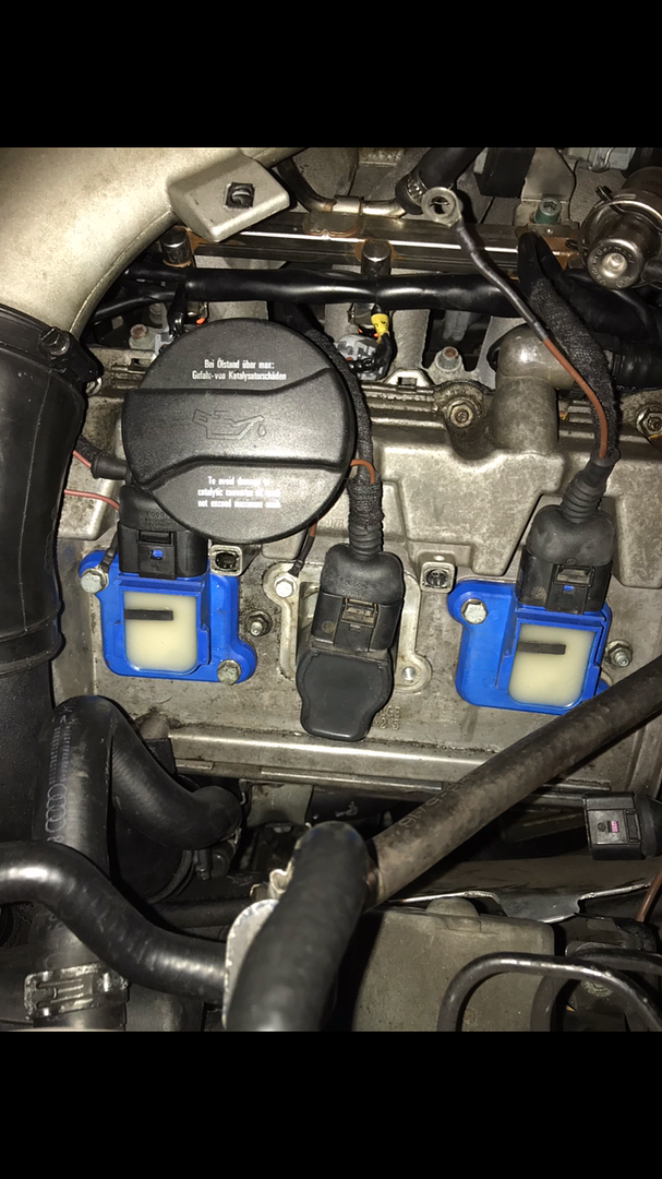
    wiring is the same on all as per pic above;

    pin 1: 12v + (red with green stripe s4 loom)
    pin 2: earthed to valve cover (brown with ring terminal)
    pin 3: signal wire (various)
    pin 4: earthed to existing harness grounds (brown with yellow stripe s4 loom)

    I've read a lot of threads about this method giving codes, some say pin 2 to harness and pin 4 to valve covers others say the opposite, i'll try re pinning to switch 2 and 4 and see what happens

  25. #65
    Senior Member Three Rings Bob Marley's Avatar
    Join Date
    Jan 18 2016
    AZ Member #
    367370
    Location
    Queens NY

    Quote Originally Posted by olethalb View Post
    wiring is the same on all as per pic above;

    pin 1: 12v + (red with green stripe s4 loom)
    pin 2: earthed to valve cover (brown with ring terminal)
    pin 3: signal wire (various)
    pin 4: earthed to existing harness grounds (brown with yellow stripe s4 loom)

    I've read a lot of threads about this method giving codes, some say pin 2 to harness and pin 4 to valve covers others say the opposite, i'll try re pinning to switch 2 and 4 and see what happens
    Pin #2 is definately Chassis ground...

    Check for good continuity to chassis ground with a meter at pin#2. I'm sorry but I'm not confident that the coil pack bolt down screw is a good grounding point. Yes its Metal to metal but the Adapter plate is not ment to be a conductor...its some kind of alloy...Most use the actual valve cover nut itself as it threads directly into the head.

    The way you have it wired now you're only connected to the valve cover...the valve cover is somewhat insulated from the cyl head with gaskets & silicone rtv etc. And therefore possibly isolated from true Chassis ground... the valve cover nut & stud go thru the valve cover straight to the cyl head itself to secure it... definately good ground there.

    This might be you're issue as you did this for all cylinders...

    and pin #2 is not vital for operation since you've got +12v, Signal & ECU Ground wired correctly wich would explain why it works.

    Found this as well...seems like you're problem. Again the fix was finding a better Ground point for Pin #2 as I'm suspecting.

    Notice Post #40 & #49

    http://www.audizine.com/forum/showthread.php?t=659099


    Sent from my SAMSUNG-SM-N920A using Tapatalk
    Last edited by Bob Marley; 11-23-2017 at 06:14 AM.
  26. #66
    Junior Member Two Rings
    Join Date
    Jan 28 2015
    AZ Member #
    311821
    Location
    Finland

    Correct way:

    PIN 2: signal ground, connect to existing wiring harness ground
    PIN 4: power ground, connect to intake manifold

  27. #67
    Senior Member Three Rings olethalb's Avatar
    Join Date
    Feb 22 2013
    AZ Member #
    110012
    Location
    london ish

    Bob - thanks for reply, i had read that thread as did as much research as possible but appreciate the second opinion

    Bindi - i read that in the other thread thanks for confirmation

    So to continue the story, armed with the above info i thought i’d pick on one coil and go from there

    Repinned 2 - 4 to match what bindi confirmed above - grounded pin 4 to coilpack mounting point for testing purposes - still threw ‘open circuit’ code

    Next i grounded pin 4 to inlet - same code

    Then i ran pin 4 to bulkhead ground behind header tank - same code

    I have a few old tfsi coils laying around so tried that, grounded to valve cover - no code


    Next for testing repinned 2 - 4 with now pin 2 grounded to valve cover - no code

    Dropped a new uprated rs6 coil in left wiring as above - threw a code

    Tried another cylinder with tfsi coil and left wiring as was - no code

    Also tried a 1.8t pencil coil as above - no code

    I guess these ‘uprated’ coils have different inners that the ecu doesn’t like

  28. #68
    Senior Member Three Rings Bob Marley's Avatar
    Join Date
    Jan 18 2016
    AZ Member #
    367370
    Location
    Queens NY

    Quote Originally Posted by olethalb View Post
    Bob - thanks for reply, i had read that thread as did as much research as possible but appreciate the second opinion

    Bindi - i read that in the other thread thanks for confirmation

    So to continue the story, armed with the above info i thought i’d pick on one coil and go from there

    Repinned 2 - 4 to match what bindi confirmed above - grounded pin 4 to coilpack mounting point for testing purposes - still threw ‘open circuit’ code

    Next i grounded pin 4 to inlet - same code

    Then i ran pin 4 to bulkhead ground behind header tank - same code

    I have a few old tfsi coils laying around so tried that, grounded to valve cover - no code


    Next for testing repinned 2 - 4 with now pin 2 grounded to valve cover - no code

    Dropped a new uprated rs6 coil in left wiring as above - threw a code

    Tried another cylinder with tfsi coil and left wiring as was - no code

    Also tried a 1.8t pencil coil as above - no code

    I guess these ‘uprated’ coils have different inners that the ecu doesn’t like
    So the solution is to ditch the fancy coils ?

    Sent from my SAMSUNG-SM-N920A using Tapatalk

  29. #69
    Senior Member Three Rings olethalb's Avatar
    Join Date
    Feb 22 2013
    AZ Member #
    110012
    Location
    london ish

    In short yes bud, £160 down the pan 😂

  30. #70
    Veteran Member Four Rings JMTx86's Avatar
    Join Date
    Oct 03 2005
    AZ Member #
    8204
    Location
    NY

    Guys, the "signal" ground is a ground at the engine.

    You can tie the grounds together but these harness are old, check your OEM harness ground, clean the eye and the surface that makes contact with the eye. You can add additional grounds as well. The coils do not draw much current at all and the OEM harness ground is more than sufficient. Regardless, Pin 2 and 4 are the same ground, neither return to the ECU.
    00 b5 s4 Single turbo
    1969 Chevy Nova 396 (Full resto, completed in 2016)
    1969 Chevy Camaro 454 (built 454/th400, body is a work in progress)
    11 Chevy z71 5.3 shop truck (Vortech V2 build in progress)

  31. #71
    Active Member One Ring
    Join Date
    Oct 05 2015
    AZ Member #
    360046
    My Garage
    B8.5 A4, B5 S4, corrado g60
    Location
    Norwood, MA USA

    👌🏻

  32. #72
    Junior Member One Ring
    Join Date
    May 01 2011
    AZ Member #
    74859
    Location
    Los Angeles

    This thread helped me a lot to resolve issues with wiring and check engine lights for a homebrew systems using 2.0 TFSI coils.

    For the record this configuration worked for me (no codes):

    PIN 2: connect to valve cover
    PIN 4: connect to existing wiring harness ground

    Reversing these connections resulted in "Intermediate open circuit" and some "Misfire" errors. I used posi-lock connectors on the ground wires to be able to quickly swap ground locations and test. Good product.
    Last edited by edshred2000; 07-20-2021 at 07:27 AM. Reason: update

  33. #73
    Veteran Member Three Rings harryn's Avatar
    Join Date
    Dec 03 2016
    AZ Member #
    387405
    My Garage
    2021 Audi A4, 2000 Audi S4, 1995 BMW M3
    Location
    Maryland

    Quote Originally Posted by edshred2000 View Post
    This thread helped me a lot to resolve issues with wiring and check engine lights for a homebrew systems using 2.0 TFSI coils.

    For the record this configuration worked for me (no codes):

    PIN 2: connect to valve cover
    PIN 4: connect to existing wiring harness ground

    Reversing these connections resulted in "Intermediate open circuit" and some "Misfire" errors. I used posi-lock connectors on the ground wires to be able to quickly swap ground locations and test. Good product.
    Got a pic of your homebrew system? I was thinking about doing the same thing, homebrew wiring that is.
    -------------------------------------------------------------------------------------------------------------------------------------------

    2021 Audi A4 S-Line Premium Plus
    2000 Audi S4 6MT
    1995 BMW M3 5MT

  34. #74
    Junior Member One Ring
    Join Date
    May 01 2011
    AZ Member #
    74859
    Location
    Los Angeles

    My "homebrew" characterization is a little misleading . I did buy the wiring "kit" from someone on this forum many years ago. It had high quality 4 pin connectors and rubber boots. I also used VW toureg plastic coil adaptors (wouldnt do that again but they have been holding up well).

    The homebrew part was the wiring that everyone seems to do on their own. If you follow carefully the instructions and wiring here you wont have a problem.

    Not sure a picture will really help you but message me privately if you really want one.

    Here is a video of another project that did it real cheap: https://www.youtube.com/watch?v=VErDw4vGvOw

  35. #75
    Veteran Member Four Rings Silverex's Avatar
    Join Date
    Nov 13 2018
    AZ Member #
    431034
    Location
    Ocean city NJ

    DIY 2.0 FSI Conversion Solder method.

    With using some of the OG wiring it seems like some guys have more issues than others. For that reason I made a harness which doesn’t use any of the factory wiring. Im running the power and signal wires straight to Ecu like some companies do only main difference is that I added a deutsch connector so it’s easier to remove during engine pulls.
    I have pins
    1: 12v+ to Ecu pin 1 on orange 10plug connector.
    2: TTL grounds tied together and bolted to intake manifold
    3: signal wires to corresponding spot in Ecu pins (94, 95, 102, 103, 110, 111)
    4: chassis grounds tied together and bolted behind coolant tank.


  36. #76
    Veteran Member Four Rings
    Join Date
    Apr 07 2011
    AZ Member #
    73609
    Location
    Home of the mighty beaver

    for those that dont feel like tackling this: https://jaeinnovations.com/collectio...wiring-harness

  37. #77
    Veteran Member Four Rings Silverex's Avatar
    Join Date
    Nov 13 2018
    AZ Member #
    431034
    Location
    Ocean city NJ

    The Tuner makes one also but without a connector you couldn’t just pull the Ecu wiring like normal during an engine pull since they have the harness going through the grommet by brake booster. The JAE one has it using the main harness grommet which is definitely a better layout. Those are great options yet don’t seem to be very popular for whatever reason. I would have went that route but I’d like to see some better sheathing for more protection and why I built my own for cheaper. While it is more work than the typical hardwire it’s not much and can be built on a bench instead of working in bay so easier in that aspect

  38. #78
    Veteran Member Four Rings
    Join Date
    Apr 07 2011
    AZ Member #
    73609
    Location
    Home of the mighty beaver

    Id love to see one that just clips into the ICM connectors.. Less work and no fussing with the ECU connectors or overlaying.

  39. #79
    Junior Member One Ring
    Join Date
    May 01 2011
    AZ Member #
    74859
    Location
    Los Angeles

    Great info on the wiring harnesses for coil conversion ! I would have gone that route if available 5+ years ago when I did the conversion.

  40. #80
    Veteran Member Four Rings Silverex's Avatar
    Join Date
    Nov 13 2018
    AZ Member #
    431034
    Location
    Ocean city NJ

    Quote Originally Posted by S4James View Post
    Id love to see one that just clips into the ICM connectors.. Less work and no fussing with the ECU connectors or overlaying.
    I was just thinking the same thing but the power wire is what was throwing me off since IIRC the ICMs only have the 6 signal wires leaving it. Plus you’d still be using the some of the stock wiring from there to Ecu but atleast the stock grounds would get deleted.

Bookmarks

Posting Permissions

  • You may not post new threads
  • You may not post replies
  • You may not post attachments
  • You may not edit your posts
  •  


    © 2001-2025 Audizine, Audizine.com, and Driverzines.com
    Audizine is an independently owned and operated automotive enthusiast community and news website.
    Audi and the Audi logo(s) are copyright/trademark Audi AG. Audizine is not endorsed by or affiliated with Audi AG.