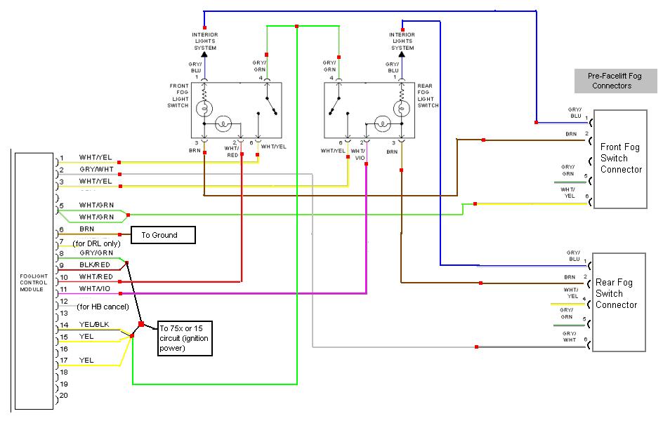
Here is how I would do it.
Notes:
- The red squares indicate splices you need to make...basically.
- I tried to keep the wire colors close for readability, but for some aren't perfect (for ex: green instead of gray/green). The jpeg compression mushes some of the colors anyhow.
- You will need a facelift fog lamp control module.
- If there's room, it is probably best to hide this in the dash behind the fog buttons or behind the radio location. That way you don't have to run wires all over the car.
- You will need a constant power source (75x or 15 circuit - ignition power) You should probably run your own fused wire from the terminals under the dash. Tapping on to the radio power may work, too. It is up to you.
- You will need a ground for the fog module. You may be able to get away with tapping onto one of the switch's grounds, but it's own chassis ground is probably best. Again, your choice.
- The power for the fog lamps will be supplied by the fog module, so make sure the power input (pin 8, 14) and power output (pin 5) are nice, heavy wires - no speaker wire.
- On a pre-facelift car, the fogs are still dependent on the fog light relay. To get full independent operation, you will want to "jump" this relay (replace this relay with a heavy jumper wire between the source and load pins). This is not necessary for operation, but is probably desirable.
- Let me know if you have any questions
- YGPM
- Other 'Ziners or electrical guru's: Please feel free to point out any flaws on my diagram. I'll be happy to make edits. It should be clear, I have *not* done this to my car, I have a facelift car. This is what I have come up with after studying the facelift and pre-facelift head lamp and fog lamp diagrams.
EDIT (7/31/2015):
After several requests, I have drawn up the diagram for the European A4 fog module as well. It has less pins and is simpler to connect (none of the nanny features that we have on the USA modules).
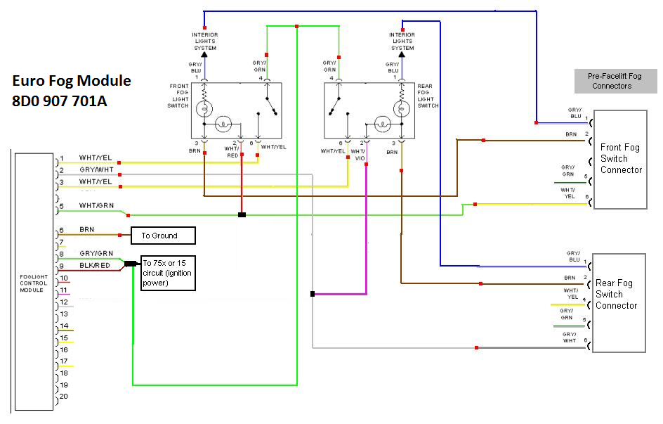
More info on the Euro Fog Module > prefacelift integration here:
http://www.audiaddict.net/viewtopic.php?f=87&t=2114
Many thanks to AZ member
down_n_dapper for his diagram request, his kind words and for his efforts testing out this scheme to confirm good operation. Cheers, mate!


 Reply With Quote


Bookmarks