I also found it interesting, that there is no longer a DIY section on the main page, hopefully we can get a subforum for DIY, there is still some of us who do our own work (nothing wrong if you dont)
So, if you guys/gals find any errors or have trouble understanding what I wrote or anything, I will revise this DIY. I also be taking better photos, once the final filter is in. Enjoy the photos and the DIY.
*I also stress, that this DIY is catered around the GSG Intake pipe, but does not take much to get to where I started off from. *
-randy
Audi 2.0t FSI Ghost Squad Garage Cold Air Intake installation – DIY by Quattro
Tools needed (ONLY for CAI install not bumper removal):
-11mm wrench or Needle nose pliers
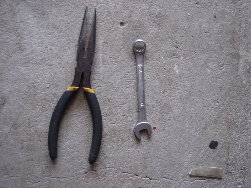
So let’s begin:
*Please note: This DIY will demonstrate how to install your new GSG CAI, with the existing GSG intake pipe. In case you have stock airbox or any other aftermarket intake set ups deviation from this guide will occur. Please follow other DIY’s on how to remove stock airbox, which can be found on EVOMS website. In this DIY, I will assume you know how to remove your stock airbox or have installed the GSG intake pipe, prior to this. Else, you must remove all components: Stock airbox/aftermarket intake, piping to the throttle body either stock, custom made or GSG piping. *
** Also in this DIY, you have the option of removing the headlight for easier installation, as I did all of this myself, made it 100x better. **
Step 1: Unwrap your new GSG CAI & couplings *not shown in pictures as I already had them prior*
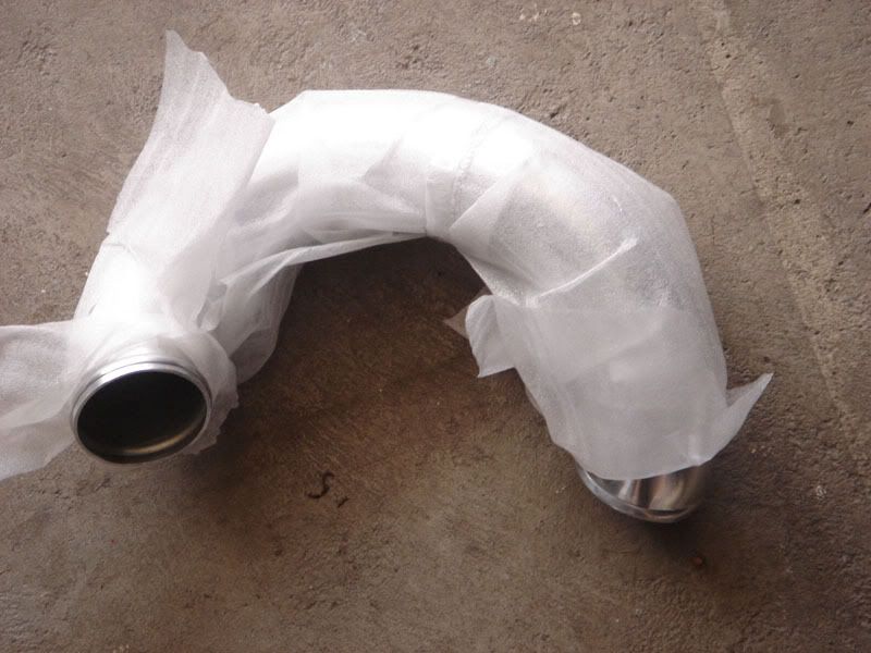
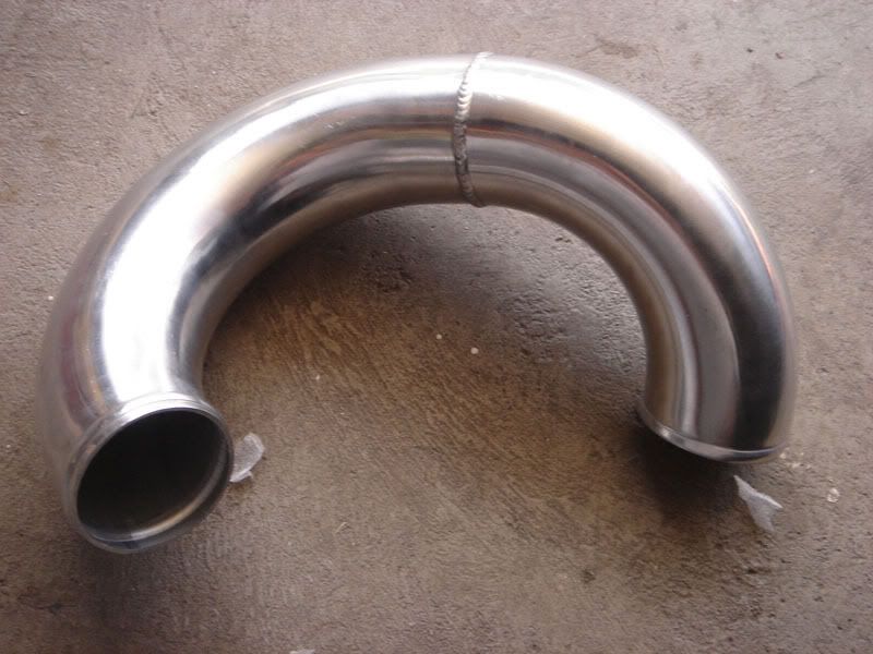
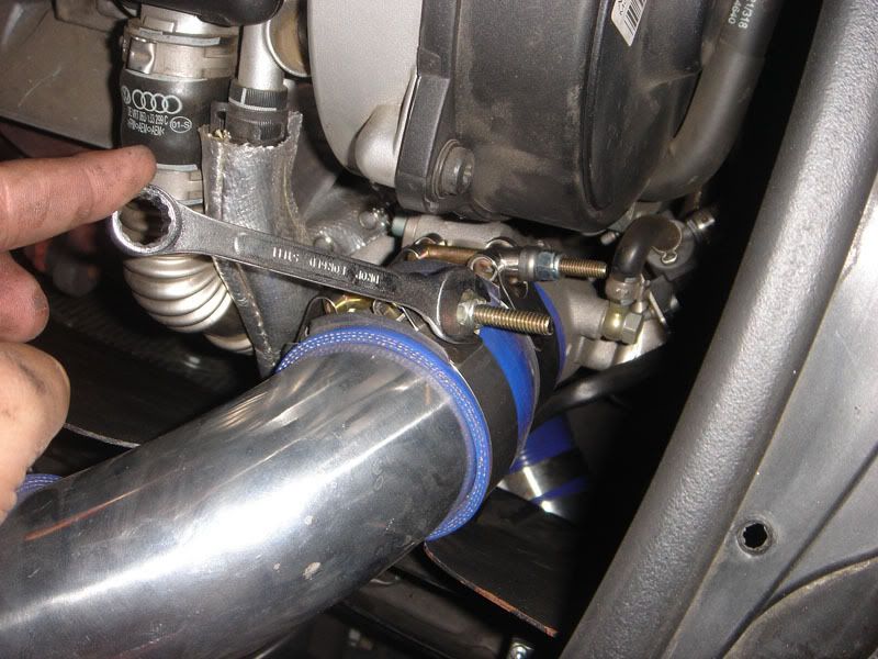
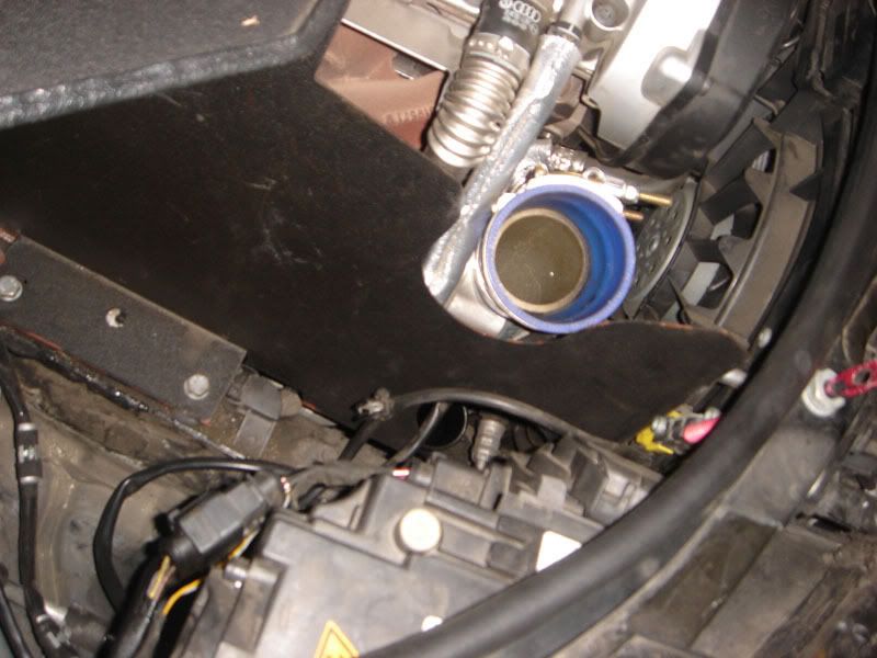
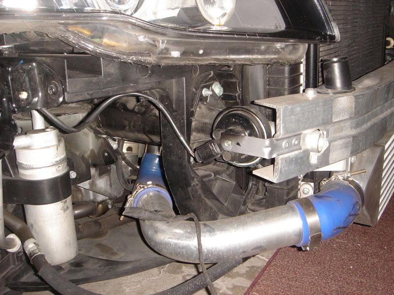
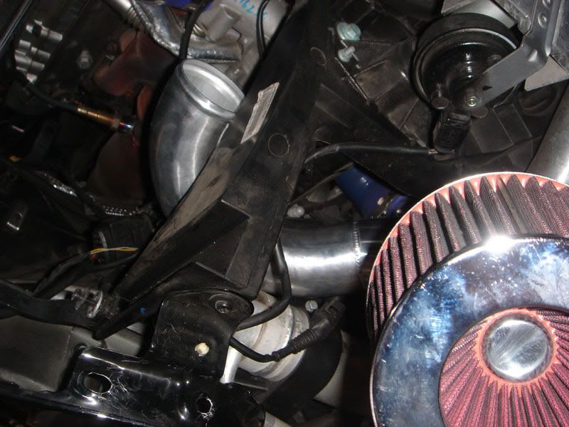
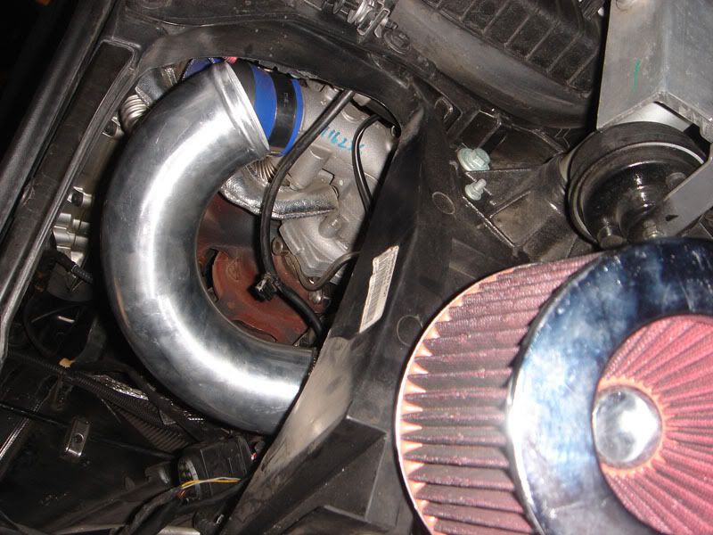
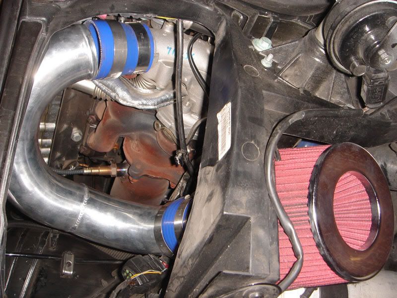
Step 2: Remove your existing GSG intake pipe from the throttle body, by loosening the t-clamp bolts. Picture 2 demonstrates the end result of the above. Picture 3 demonstrates the area where the pipe will be placed.
 (Picture 1)
 (Picture 2)
 (Picture 3)
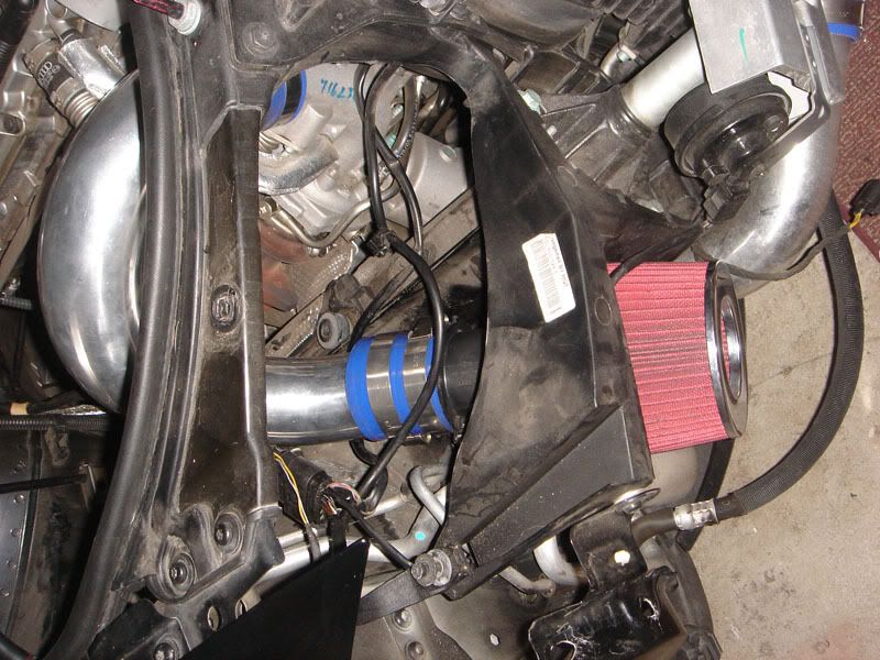
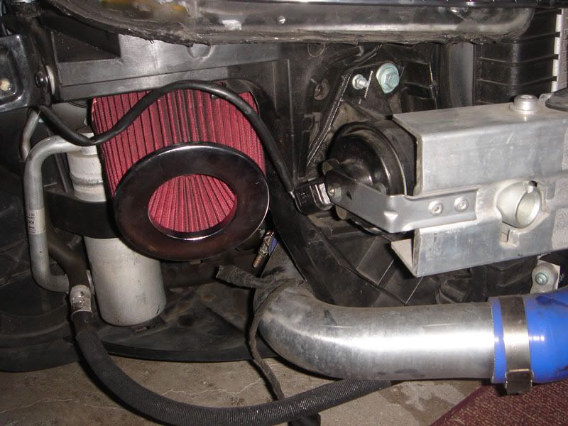
Step 3: Attach the MAF to one of the couplings (2.75 to 2.75). Use either your pillar or 11mm wrench to tighten the MAF to the intake pipe as well as the filter to the end of the MAF.
*NOTE 1: Make sure the MAF arrow is pointing AWAY from the intake filter.
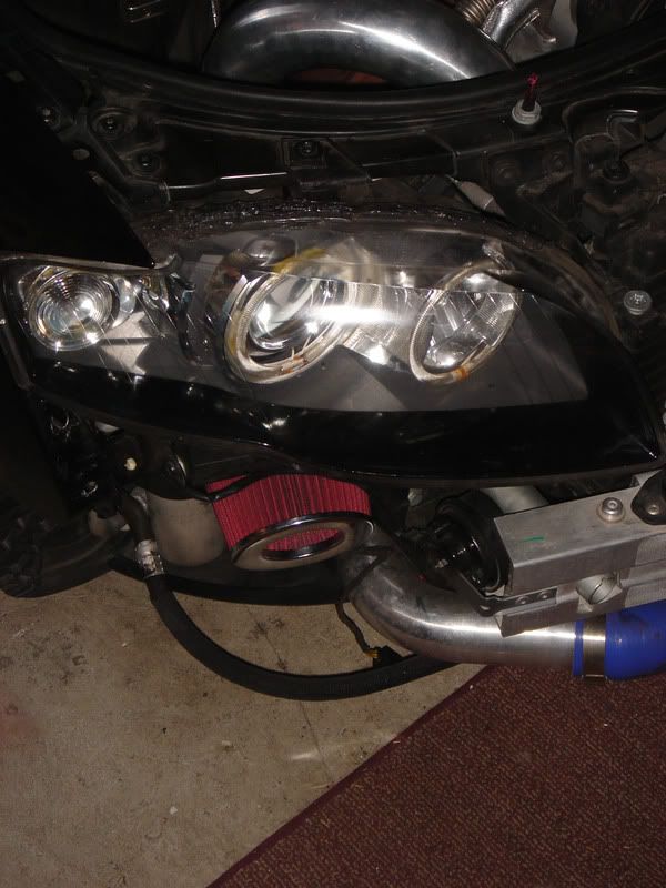
*Note 2: I would suggest having the MAF sensor connection to the left as pictured in the photo. I suggest this, because if you need to remove the intake for any reason, this location would be the most accessible. Another reason is because the plug might not reach if facing the other way AND lastly, you run the risk of the plug hitting the bottom of the headlight.
*Note 3: The second picture is the exact way the intake installs. This is the optimal positioning for the pipe, so please make sure your intake pipe looks like this when installing.
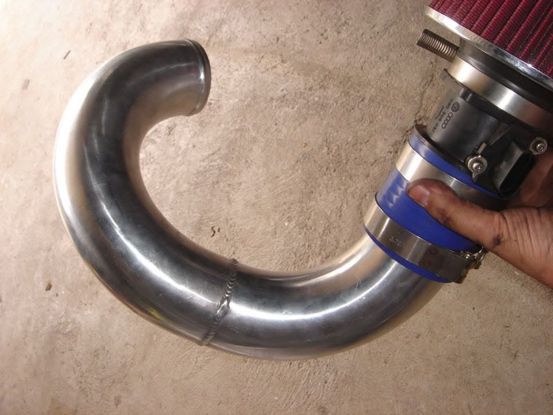 (Picture 1)
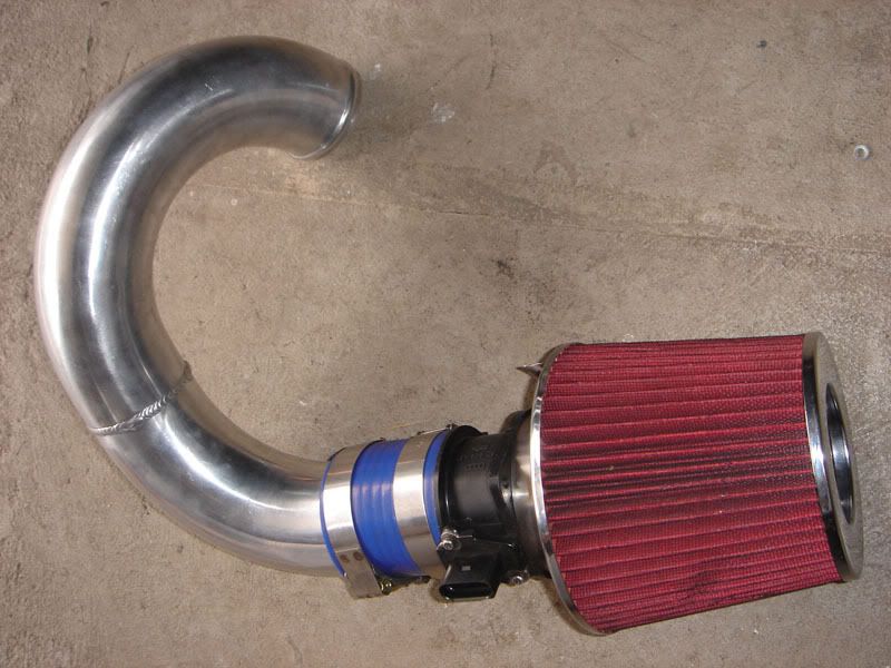 (Picture 2)


 Reply With Quote
 (Picture 1)
 (Picture 2)
 (Picture 3)
 (Picture 4)


Bookmarks