Audizine - An Automotive Enthusiast Community

Results 1 to 2 of 2
  1. #1
    Registered Member One Ring
    Join Date
    Jan 13 2006
    AZ Member #
    9682
    Location
    Martinsburg, WV

    ECM(for ECT) Diagram

    Guest-only advertisement. Register or Log In now!


    OK.
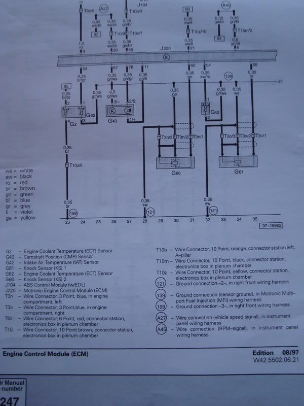
    So i finally have a diagram of the ECT temp sensor going to the ECM.
    Correct me if I'm reading this wrong, In the picture the G2 is the ect sensor and on the sensor are 4 terminals.

    terminal 1 - going to ECM
    terminal 2 - going to the instrument cluster?
    terminal 3 - going to ground?
    terminal 4 - going to ground?

    My question is:

    Can I just ground terminal 3 and 4 to a bolt or something that is outside the ECM module?

    Thanks

  2. #2
    Senior Member Two Rings KevinA41.8T's Avatar
    Join Date
    Nov 30 2005
    AZ Member #
    9026
    Location
    CONNECTICUT

    Re: ECM(for ECT) Diagram

    in this diagram its impossible to know where 2 and three are going. you need the whole wiring diagram. ill look it up when i find some motivation.
    2000 S4 IMOLA - CCW CLASSICS 18X9 18X10 - STASSIS TRACKSPORTS 700/800 - ASP DTS - STERN MOUNTS - 034 DP'S - ASP TRU DUAL - CUSTOM INTAKE/CATCH CAN - VAST METH - AEM WIDEBAND - RS4 INTERCOOLERS - JFONZ TUNED

Bookmarks

Posting Permissions

  • You may not post new threads
  • You may not post replies
  • You may not post attachments
  • You may not edit your posts
  •  


    © 2001-2024 Audizine, Audizine.com, and Driverzines.com
    Audizine is an independently owned and operated automotive enthusiast community and news website.
    Audi and the Audi logo(s) are copyright/trademark Audi AG. Audizine is not endorsed by or affiliated with Audi AG.